TM1629_TM1630_TM1631.The explanation document of the parameters on simplified GUI.pdf - 第7页
SMT Software Engineering Group IM Operations Y AMAHA MOT OR CO.,L TD MDOC-SO FT50035 7/34 1.4. C heck Center Brightness Suitable for dist inguishing bet ween the top a nd bottom faces of c hip components.…
SMT Software Engineering Group
IM Operations
YAMAHA MOTOR CO.,LTD
MDOC-SOFT50035
6/34
+0 ゚
+180 ゚
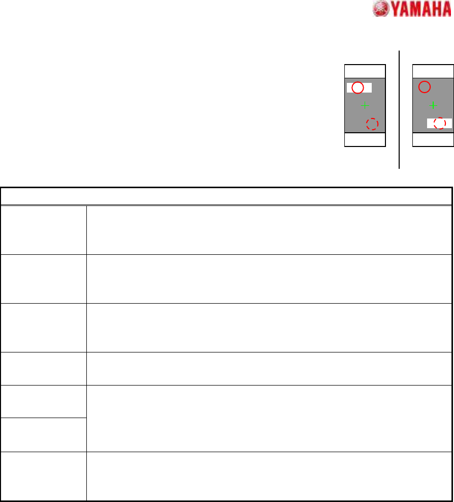
1.3. Check Direction
Suitable for identifying a chip component's direction.
A direction judgment is made by comparing the average brightness of
the specified circle area with a 180 degrees opposing circle area.
Suitable where a polarity mark, etc., exists on the recognition face.
Particular parameters
Check Type When it is expected that the brightness of the specified circle will be brighter
than the brightness of a rotation symmetry position, “White” is specified. Else
“Black” is specified.
Check Direction The direction at which a direction judging is performed is specified.
In distinguishing 0 and 180 degrees, “2 Angle” is specified. In distinguishing 0,
90, 180, and 270 degrees, “4 Angle” is specified.
Min. Brightness
Difference
The difference in the average brightness of detection circles being checked in
order to differentiate the directions must be larger than this value, or an error will
occur. If 0, 50 will be set.
Direction Mark
Diameter (mm)
The diameter of the circle where brightness is measured is specified.
Direction Mark
Center X
Direction Mark
Center Y
The center position of the circle where brightness is measured is specified.
(Origin: The component center)
Check Many
Adsorption
It confirms whether excessive components exist. When the “Check” is specified,
it becomes an error if excessive edges exist around the detected component.
*Cannot use this parameter on VGOS V2.xx and YGOS V2.xx.
SMT Software Engineering Group
IM Operations
YAMAHA MOTOR CO.,LTD
MDOC-SOFT50035
7/34
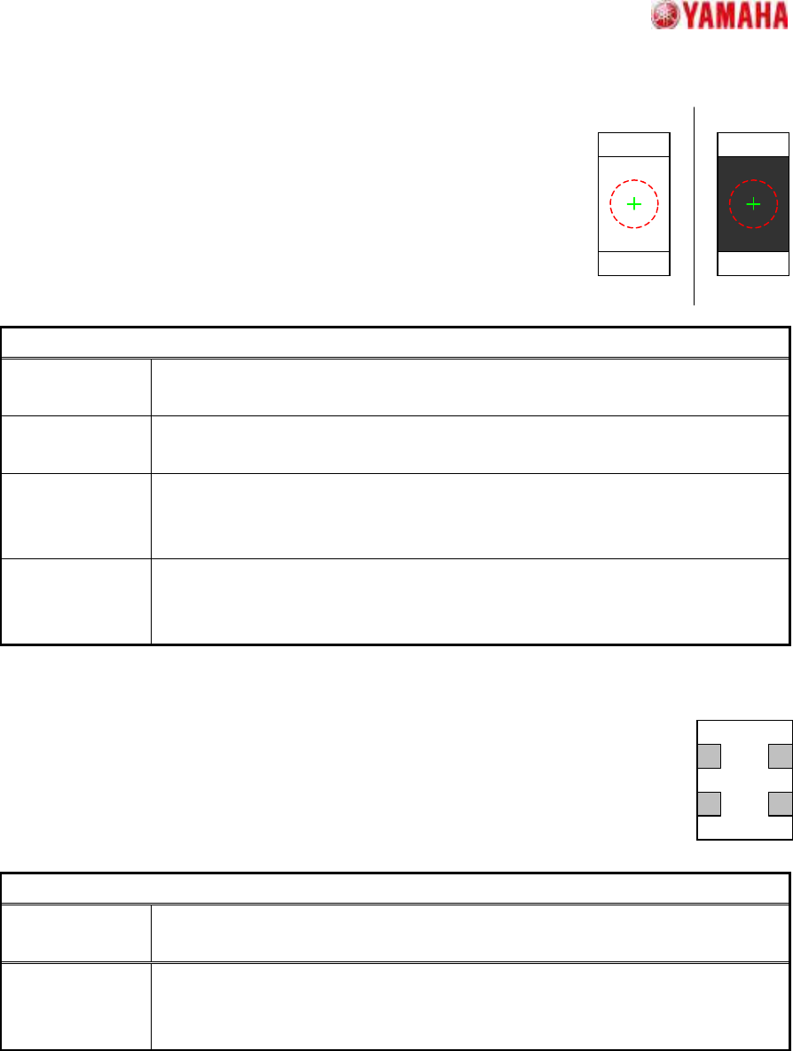
1.4. Check Center Brightness
Suitable for distinguishing between the top and bottom faces of chip
components.
The top/bottom judgment is made by measuring the average
brightness at the component center (circle area).
Particular parameters
Check
Threshold
The average brightness of the measurement circle is compared with the value
set up here, and turnover judging is performed.
Check Diameter
(mm)
The diameter of the measurement circle is specified.
NG Type An error judging condition is specified. In the case of “Black”, it will become an
error if the average brightness of the measurement circle is darker than the
“Check Threshold”. In the case of “White”, it becomes the contrary.
Check Many
Adsorption
It confirms whether excessive components exist. When the “Check” is specified,
it becomes an error if excessive edges exist around the detected component.
*Cannot use this parameter on VGOS V2.xx and YGOS V2.xx.
1.5. Retry Lead Center Search
Suitable for chip shape components where the west to east direction edge position is
unclear.
Particular parameter
Angle Correction
Under the influence of the fine projection on the detecting line, when angle
accuracy is not good, if it turns “On”, angle accuracy will be improved.
Check Many
Adsorption
It confirms whether excessive components exist. When the “Check” is specified,
it becomes an error if excessive edges exist around the detected component.
*Cannot use this parameter on VGOS V2.xx and YGOS V2.xx.
OK NG
SMT Software Engineering Group
IM Operations
YAMAHA MOTOR CO.,LTD
MDOC-SOFT50035
8/34
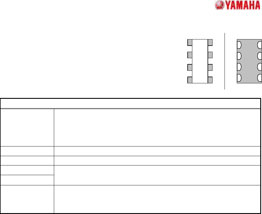
1.6. Chip Array
Suitable for array type chip components which is aligned with
electrodes.
Recognition methods are different by the "Lead Type" setting.
Particular parameters
Ruler Width The width of a detection line is specified. It is about 70 micrometers per preset
value 1. If a larger value is set up in the range which does not exceed the
length whose lead width is stable, it becomes hard to be influenced by a noise
etc.
Lead Number The single-sided lead number is specified.
Lead Pitch (mm) The lead pitch is specified.
Lead Width (mm)
ReflectLL (mm)
The size of the lead section is specified.
Lead Type The form of an electrode is specified.
In the case of form like left-hand side, “Convex (Register)” is specified, and
right-hand side, “Flat (Capacitor)” is specified.