TM1629_TM1630_TM1631.The explanation document of the parameters on simplified GUI.pdf - 第31页
SMT Software Engineering Group IM Operations Y AMAHA MOT OR CO.,L TD MDOC-SO FT50035 31/34 +0 ゚ +180 ゚ 14. Sp. Quad 14.1. Check Direction Suitable for det ermining the di rection of r ectangular com pon…
SMT Software Engineering Group
IM Operations
YAMAHA MOTOR CO.,LTD
MDOC-SOFT50035
30/34
13.6. 2 Objects (Angle of Terminal)
Suitable for components with 2 distinctive terminals, where an angular offset is
desired at the straight line at the terminal end faces.
The component center is the average center of gravity position of the 2 terminals,
and the angle is the tilt of the terminal end-face straight line.
Particular parameters
Method of Auto
Binarize
The method of binarizing is specified. This parameter is effective only
when the threshold is 0.
Brightness
Distinction
It searches for the threshold which improves separation of
white and black most automatically. It is suitable when the
brightness difference of a terminal section and a base
section is big.
Area Size
Distinction
A threshold is determined that the area judged as white
equal to the area defined as terminals. It is suitable when
there is nothing to reflect in addition to terminals.
Binary Level Correction
This parameter is effective only when the “Threshold” is 0, and when
“Method of Auto Binarize” is “Area Size Distinction”. When there is a
portion which looks white in addition to the terminals for detection, the
rate to the terminal area of the portion is specified.
Max Angle-Correction
(deg)
When the difference of the angle of the line which connects the
center-of-gravity of up and down terminals, and the angle of the straight
line of the outline of terminals is larger than the specified value, it
becomes an error.
Terminal Width (mm)
Terminal Length (mm)
The size of terminals is specified. If “0” is set as “Terminal Length”,
terminal shape becomes circular and “Terminal Width” is a diameter.
Find PosY (mm) The terminal’s center of gravity in a perpendicular direction is specified.
(Origin: The center of component)
SMT Software Engineering Group
IM Operations
YAMAHA MOTOR CO.,LTD
MDOC-SOFT50035
31/34
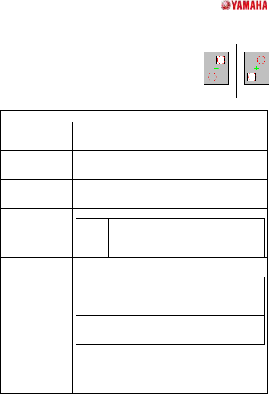
+0 ゚ +180 ゚
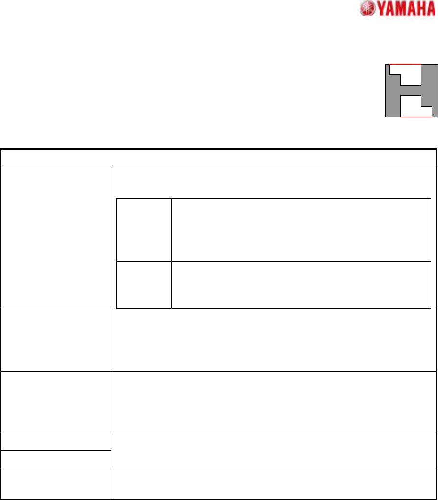
14. Sp. Quad
14.1. Check Direction
Suitable for determining the direction of rectangular components.
A direction judgment is made by comparing the average brightness of
the specified circle area with a 180 degrees opposing circle area.
Suitable where a polarity mark, etc., exists on the recognition face.
Particular parameters
Check Type When it is expected that the brightness of the specified circle will be
brighter than the brightness of a rotation symmetry position, “White” is
specified. Else “Black” is specified.
Check Direction The direction at which a direction judging is performed is specified.
In distinguishing 0 and 180 degrees, “2 Angle” is specified. In
distinguishing 0, 90, 180, and 270 degrees, “4 Angle” is specified.
Min. Brightness
Difference
The difference in the average brightness of detection circles being
checked in order to differentiate the directions must be larger than this
value, or an error will occur. If 0, 50 will be set.
Center Detection
Algorithm
The calculation method of the component center is specified.
Center of
Gravity
The center-of-gravity of the detected contour.
Apex of
Rectangle
The center of the rectangle which consists of detected
lines.
Method of Auto Binarize The method of binarizing is specified. This parameter is effective only
when the threshold is 0.
Brightness
Distinction
It searches for the threshold which improves separation
of white and black most automatically. It is suitable when
the brightness difference of a terminal section and a
base section is big.
Area Size
Distinction
A threshold is determined that the area judged as white
equal to the area defined as terminals. It is suitable
when there is nothing to reflect in addition to terminals.
Direction Mark Diameter
(mm)
The diameter of the circle where brightness is measured is specified.
Direction Mark Center X
Direction Mark Center Y
The center position of the circle where brightness is measured is
specified.
(Origin: The component center)
SMT Software Engineering Group
IM Operations
YAMAHA MOTOR CO.,LTD
MDOC-SOFT50035
32/34
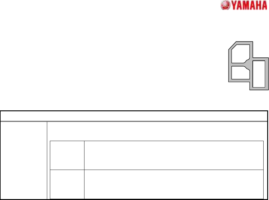
14.2. Shield Frame
Suitable for shield components.
The component angle is the tilt of the dominant straight lines that form the
component contour, and the component center is the center of that angle's
circumscribed rectangle. The outer contour comprises mostly horizontal and
vertical straight lines, and all the resulting component contours must be
connected.
Particular parameter
Method of Auto
Binarize
The method of binarizing is specified. This parameter is effective only when the
threshold is 0.
Brightness
Distinction
It searches for the threshold which improves separation of white
and black most automatically. It is suitable when the brightness
difference of an object and background is big.
Area Size
Distinction
A threshold is determined that the area judged as white equal to
the area defined as balls. It is suitable when there is nothing to
reflect in addition to an object.