TM1629_TM1630_TM1631.The explanation document of the parameters on simplified GUI.pdf - 第24页
SMT Software Engineering Group IM Operations Y AMAHA MOT OR CO.,L TD MDOC-SO FT50035 24/34 12. Special 12.1. Side Lead Fitting Suitable f or com ponent s with le ads of diff erent shapes and pitches i n t…
SMT Software Engineering Group
IM Operations
YAMAHA MOTOR CO.,LTD
MDOC-SOFT50035
23/34
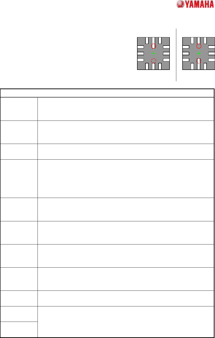
11.4. Check Direction
Suitable for determining the direction of PLCC and QFP
components.
A direction judgment is made by comparing the average
brightness of the specified circle area with a 180 degrees
opposing circle area. Suitable where a polarity mark, etc., exists
on the recognition face.
Particular parameters
Lead Search The position used as the datum of positioning is specified. In the case of "Top",
outward lead tip section is detected, and in the case of "Root", inner lead tip
section is detected.
Excessive
Lead Check
If “Check” is specified, when the component whose lead pitch and width are same
and which have excessive leads is supplied, it becomes an error. In “No Check”,
the check is not performed.
Lead Search
Filter
The amount of application of luminescent spot removal is specified.
Right Angle
Fitting
The extraction method of side leads is specified. If “Off”, the extraction method by
the usual distance relation is applied. If “On”, the method which give priority to the
degree of rectangular cross of two sides is applied. Usually, it specified “Off”.
When the right side leads which have the section with luminosity unevenness are
hard to be detected, if “On” is specified, a recognition rate will increase.
Check Type When it is expected that the brightness of the specified circle will be brighter than
the brightness of a rotation symmetry position, “White” is specified. Else “Black” is
specified.
Check
Direction
The direction at which a direction judging is performed is specified.
In distinguishing 0 and 180 degrees, “2 Angle” is specified. In distinguishing 0, 90,
180, and 270 degrees, “4 Angle” is specified.
Judgment
Method
Action after a direction check is specified. When the "Error" is specified, if an
angle difference is detected, it becomes an error. An angle is compensated when
"Angle Correction" is specified.
Min.
Brightness
Difference
The difference in the average brightness of detection circles being checked in
order to differentiate the directions must be larger than this value, or an error will
occur. If 0, 50 will be set.
Direction Mark
Diameter (mm)
The diameter of the circle where brightness is measured is specified.
Direction Mark
Center X
Direction Mark
Center Y
The center position of the circle where brightness is measured is specified.
(Origin: The component center)
+0 ゚ +180 ゚
SMT Software Engineering Group
IM Operations
YAMAHA MOTOR CO.,LTD
MDOC-SOFT50035
24/34
12. Special
12.1. Side Lead Fitting
Suitable for components with leads of different shapes and pitches in the
same direction.
Setting is possible for up to 4 directions x 2 groups. When the end lead is
detected, the positional relationship of the leads is checked, and the pairing
that most closely matches the component definition is selected in order to
increase the recognition rate.
Particular parameters
Excessive Lead
Check
If “Check” is specified, when the component whose lead pitch and width are
same and which have excessive leads is supplied, it becomes an error. In “No
Check”, the check is not performed.
Lead Length
Tolerance (mm)
If the difference between the straight line which is applied at the tip of leads and
each lead tip is larger than the value set up here, it becomes an error.
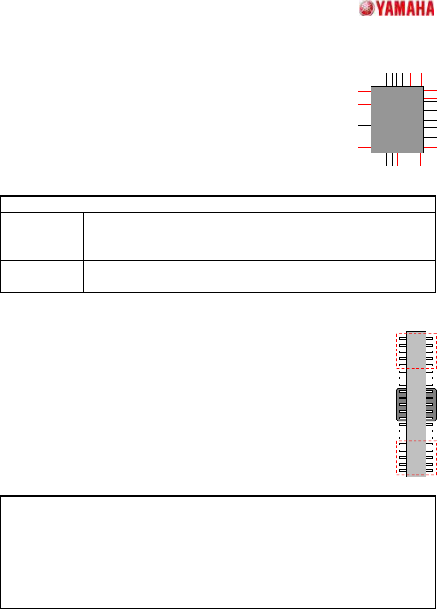
12.2. Long Connector
Suitable for components where the lead ends in the center vicinity cannot be detected
properly due to the pickup clip, etc
Although the lead quantity check, etc., occurs in the usual manner, only the specified
both-ends lead quantity is used for positioning.
Particular parameters
Detecting Numbers
of side lead
The lead number used for positioning is specified. The number per end and
side are specified. (If “5” is specified, it becomes what is shown by the red
frame of the above figure.)
Excessive Lead
Check
If “Check” is specified, when the component whose lead pitch and width are
same and which have excessive leads is supplied, it becomes an error. In
“No Check”, the check is not performed.
SMT Software Engineering Group
IM Operations
YAMAHA MOTOR CO.,LTD
MDOC-SOFT50035
25/34
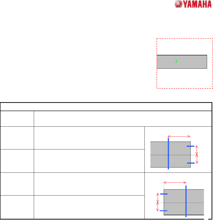
13. As Mark
13.1. Mark Line
Suitable for rectangular components like that shown in the figure,
where part of the contour may extend beyond the detection
range.
When part of the contour extends beyond the detection range,
the center and angle are estimated based on the remaining sides.
Suitable for components with contours that contain uneven sections,
because the scan line position can be freely specified.
Particular parameters
Detect
Direction
The direction (which a projection does not generate) used for detection is specified.
Usually, “Auto” is specified.
Right Line
Offset (mm)
The distance of “A” in the figure is specified. When
“0” is specified, one fourth of detected X size is
applied.
Right Center
Offset (mm)
The distance of “B” in the figure is specified. When
“0” is specified, one fourth of detected Y size is
applied.
Left Line
Offset (mm)
The distance of “C” in the figure is specified. When
“0” is specified, one fourth of detected X size is
applied.
Left Center
Offset (mm)
The distance of “D” in the figure is specified. When
“0” is specified, one fourth of detected Y size is
applied.
A
B
C
D