TM1629_TM1630_TM1631.The explanation document of the parameters on simplified GUI.pdf - 第16页
SMT Software Engineering Group IM Operations Y AMAHA MOT OR CO.,L TD MDOC-SO FT50035 16/34 OK NG A 8. Mini-T r/SOT 8.1. C heck Ups i de-Down Suitable f or top/bottom j udgments at mini transistor an…
SMT Software Engineering Group
IM Operations
YAMAHA MOTOR CO.,LTD
MDOC-SOFT50035
15/34
OK NG
A
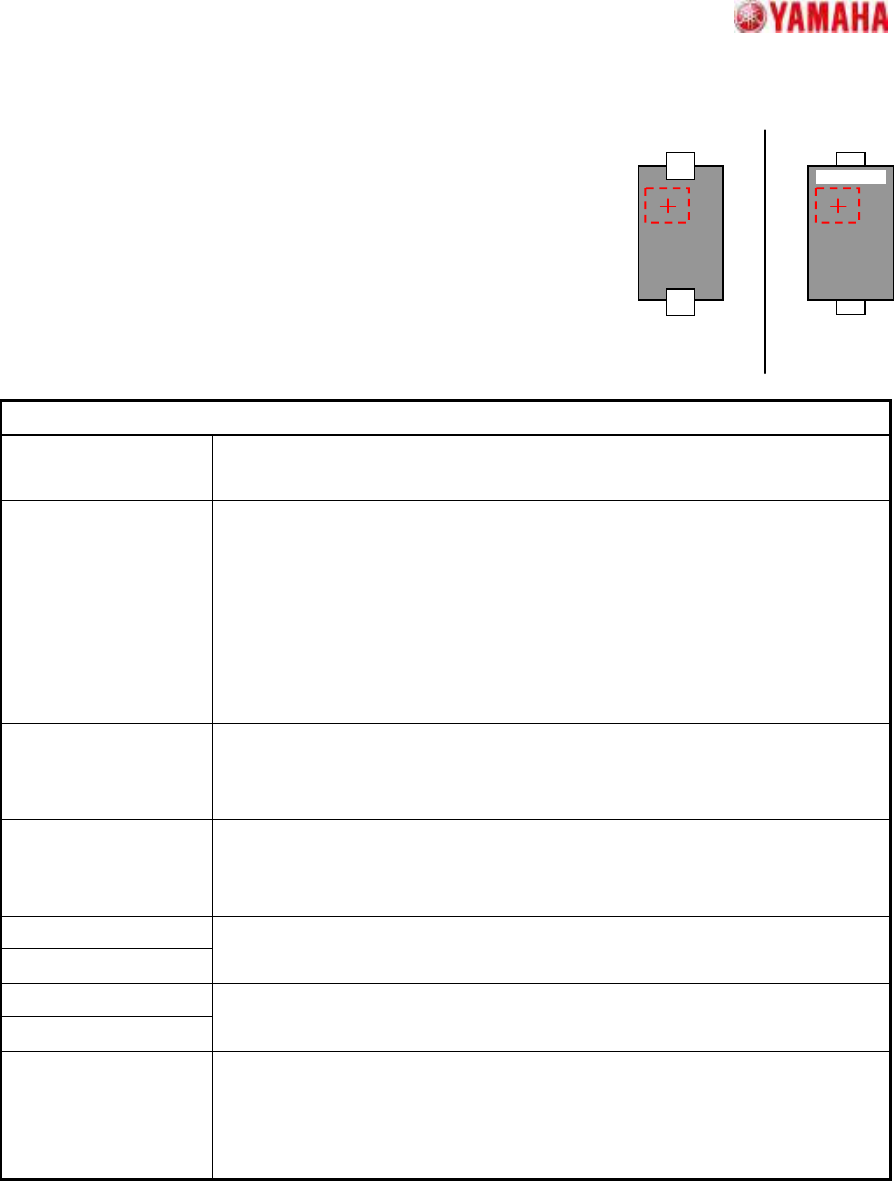
7.2. Check Upside-Down
Suitable for top/bottom judgments at components with 2 leads,
such as 2-terminal diodes.
The component top/bottom judgment occurs by checking the
brightness variation (dispersion) at the specified judgment area.
Suitable when printed characters, etc., are present at the mold area
of the pickup face.
Particular parameters
Threshold of 3-sigma
The threshold of the brightness variation for check is specified. The value
specified here is compared with the brightness variation in the check area.
Threshold of Average
Usually, “0” is specified. A superfluous judging may be prevented by setting
up values other than “0”. When a value other than “0” is set up, It becomes
an error when the following three conditions are fulfilled.
1. “Dispersion” is specified as “NG Condition”.
2. The brightness variation in the check area is over the value specified
as “Threshold of 3-sigma”.
3. The average brightness in the check area is larger than this.
Check-area Offset
Enable
When “Enable” is specified, the check area is moved according to the value
specified as “Check-area Offset”. When “Disable” is specified, the check
area is set as the center of the component.
NG Condition When “Dispersion” is specified, it becomes an error when the measured
value is larger than the value specified as “Threshold of 3-sigma”
parameter. In the case of “Non Dispersion”, it becomes the contrary.
Check-area Size X
Check-area Size Y
The size of the check area is specified.
Check-area Offset X
Check-area Offset Y
Offset of the check area is specified.
(Origin: The component center)
Check Many
Adsorption
It confirms whether excessive components exist. When the “Check” is
specified, it becomes an error if excessive edges exist around the detected
component.
*Cannot use this parameter on VGOS V2.xx and YGOS V2.xx.
SMT Software Engineering Group
IM Operations
YAMAHA MOTOR CO.,LTD
MDOC-SOFT50035
16/34
OK
NG
A
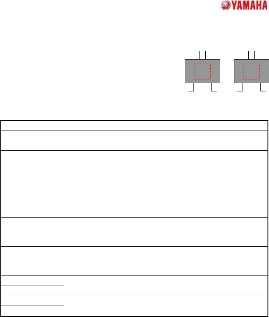
8. Mini-Tr/SOT
8.1. Check Upside-Down
Suitable for top/bottom judgments at mini transistor and SOT
components.
The component top/bottom judgment occurs by checking the
brightness variation (dispersion) at the specified judgment area.
Suitable when printed characters, etc., are present at the mold
area of the pickup face.
Particular parameters
Threshold of 3-sigma
The threshold of the brightness variation for check is specified. The value
specified here is compared with the brightness variation in the check area.
Threshold of Average
Usually, “0” is specified. A superfluous judging may be prevented by setting
up values other than “0”. When values other than “0” is set up, It becomes
an error when the following three conditions are fulfilled.
1. “Dispersion” is specified as “NG Condition”.
2. The brightness variation in the check area is over the value specified
as “Threshold of 3-sigma”.
3. The average brightness in the check area is larger than this.
Check-area Offset
Enable
When “Enable” is specified, the check area is moved according to the value
specified as “Check-area Offset”. When “Disable” is specified, the check
area is set as the center of the component.
NG Condition When “Dispersion” is specified, it becomes an error when the measured
value is larger than the value specified as “Threshold of 3-sigma”
parameter. In the case of “Non Dispersion”, it becomes the contrary.
Check-area Size X
Check-area Size Y
The size of the check area is specified.
Check-area Offset X
Check-area Offset Y
Offset of the check area is specified.
(Origin: The component center)
SMT Software Engineering Group
IM Operations
YAMAHA MOTOR CO.,LTD
MDOC-SOFT50035
17/34
OK
NG
9. SOP
9.1. Side Lead Fitting
Suitable for SOP components where the lead reflection is uneven, with
recognition not possible in the "Normal" algorithm.
When the end lead is detected, the positional relationship of the leads is
checked, and the pairing that most closely matches the component definition is
selected in order to increase the recognition rate.
Particular parameter
Excessive
Lead Check
If “Check” is specified, when the component whose lead pitch and width are same
and which have excessive leads is supplied, it becomes an error. In “No Check”,
the check is not performed.
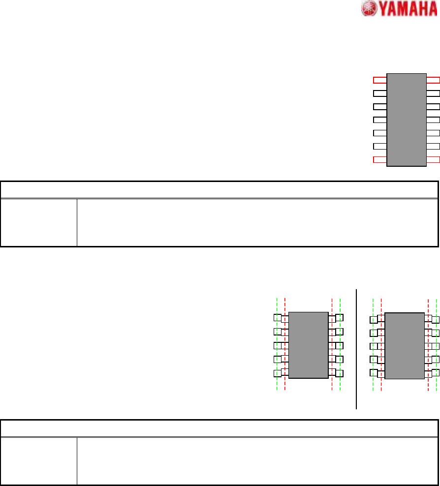
9.2. Check Upside-Down
Suitable for top/bottom judgments at SOP components.
Near the lead tip and base pitches are compared to
check for upside-down components. This recognition
algorithm is effective when using a single camera. In
multi-camera formats, recognition is possible by lining the
leads up in the N/S direction.
Particular parameter
Excessive
Lead Check
If “Check” is specified, when the component whose lead pitch and width are same
and which have excessive leads is supplied, it becomes an error. In “No Check”,
the check is not performed.