00196430-0102-AI_Head_Reconfiguration_Kit_SX_CPP_en_de.pdf - 第51页
Brief Description SIPLACE SX 1 Head Modularity SX 70x Assembly Instructions / Montageanleitung Head Reconfiguration K it CPP 51 Head Modula rity SX 7 0x 2.4 Head Modularity SX 70x The CPP head can either be insta lled in…

Brief Description
Requirements and Restrictions for the CPP Placement Head Reconfiguration Duration
50 Assembly Instructions / Montageanleitung Head Reconfiguration Kit CPP
Requirements and Restrictions for the CPP Placement Head
2.3 Requirements and Restrictions for the CPP Placement Head
▪ The camera type is added during the configuration query of the head reconfiguration kit. The C&P
component camera (type 29) 27x27 digital RK [03018637-xx] is the default.
– [03018637-xx] C&P component camera (type 29) 27x27 digital RK (default)
– [00119783-xx] CPP head camera (01005) (type 38)
▪ In a placement area with 2 gantries the CPP heads may only be installed on the same height. Thus,
both CPP heads have to be installed in either the high or the low position.
▪ If the CPP head is used together with a TwinHead in a placement area with 2 gantries, the CPP head
may only be installed in the high position.
▪ When using third party feeder modules pay particular attention on the crash danger.
▪ It is not possible to use a vacuum pump together with a CPP head. The head principle requires a
compressed air supply for the time being.
▪ During the placement of a PCB no nozzle change is executed with CPP heads (applies to old modes:
C&P, P&P and Mixed).
▪ In conjunction with a stationary camera the CPP head must always be installed in the high position
and the stationary camera in the low position.
▪ The CPP head can only be used with stationary cameras of function status -04 or higher.
▪ When using a CPP head no magazines of the C&P20A head are allowed on the nozzle changer.
This is monitored by the software.
Reconfiguration Duration
2.3.1 Reconfiguration Duration
The following reconfiguration durations per head can be expected:
Placement head Single-/Double conveyor Task
Disassembling CPP 20 min Without options such as nozzle changers, verify
component reject bin and stationary camera
Disassembling
C&P20A
20 min Without options such as nozzle changer, verify
component reject bin
Disassembling Twin
-
Head
30 min Verify Component reject bin
Assembling CPP 90 / 120 min With mapping and without options such as nozzle
changer, verify component reject bin and stationary
camera
Assembling C&P20A 90 / 120 min With mapping and without options such as nozzle
changer, query component reject bin
Assembling Twin
-
Head
90 / 120 min With mapping and without options such as nozzle
changer, verify component reject bin and stationary
camera

Brief Description
SIPLACE SX 1 Head Modularity SX 70x
Assembly Instructions / Montageanleitung Head Reconfiguration Kit CPP 51
Head Modularity SX 70x
2.4 Head Modularity SX 70x
The CPP head can either be installed in a high or a low position.
The following terms mean:
▪ Installation position low: CPP_L corresponds to a component height of 6 mm maximum.
▪ Installation position high: CPP_H corresponds to a component height of 11.5 mm maximum.
The following head configuration options are available:
SIPLACE SX 1
2.4.1 SIPLACE SX 1
Head configurations on the SIPLACE SX 1
SIPLACE SX 2
2.4.2 SIPLACE SX 2
Head configurations on the SIPLACE SX 2
Gantry 1 Default cameras Options
C&P20A STT 23 ----
CPP_H SST 29 Component camera SST 38
Stat. camera SST 33 (from FS 04 and in low installation posi
-
tion only)
CPP_L SST 29 Component camera SST38
TwinHead SST 33 Stat. camera SST 25 (location 1 only)
3D coplanarity module ST 37 (location 1 only)
Gantry 1 / Gantry 2 Default cameras Options
C&P20A / C&P20A STT 23 ----
CPP_H / CPP_H SST 29 Component camera SST 38
Stat. camera SST 33 possible on location 1 and
2 (from FS 04 and in low installation position on
-
ly)
CPP_L / CPP_L SST 29 Component camera SST38
CPP_H / TwinHead STT 29 (on gan
-
try 1)
Twin SST33 (on
gantry 2)
CPP:
Component camera SST 38
Stat. camera SST 33 (from FS 04 and in low in
-
stallation position only)
TwinHead:
Stat. camera SST 25 (location 1 only)
3D coplanarity module SST 37 (location 1 only)
TwinHead / TwinHead SST 33 Stat. camera SST 25 (location 1 only)
3D coplanarity module ST 37 (location 1 only)
Brief Description
Sequence of the Placement Head Exchange Disassembly Sequence
52 Assembly Instructions / Montageanleitung Head Reconfiguration Kit CPP
Sequence of the Placement Head Exchange
2.5 Sequence of the Placement Head Exchange
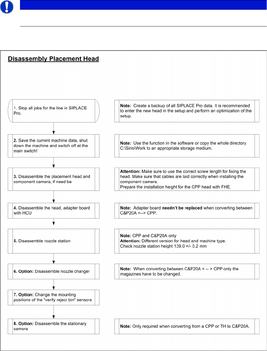
Disassembly Sequence
2.5.1 Disassembly Sequence
NOTICE
The flow charts describe the general procedure for switching between different placement head
types on SX1/2 machines from SW70x.