00196430-0102-AI_Head_Reconfiguration_Kit_SX_CPP_en_de.pdf - 第60页
Installing the CPP Placement Head Disassembling the TwinHead Conversion of the Head Adapter 60 Assembly Instructions / Montageanleitung Head Reconfiguratio n Kit CPP Fitting the HCU onto the base adapter for CPP and C&am…
Installing the CPP Placement Head
Further Aspects for the Configuration Disassembling the TwinHead
Assembly Instructions / Montageanleitung Head Reconfiguration Kit CPP 59
► Remove the stationary camera. Further information can be found in the Service Manual SX 1/2
[00196497-xx] in the section describing the exchange of the stationary component camera.
The reject bin of the stationary camera can be kept when changing over to a CPP head. When changing
over to a C&P20A head the reject bin must be removed. Further information can be found in the Assem
-
bly Instructions "Reject Bin SX1/2 [00196615] or in the Assembly Instructions "Stationary Camera SI
-
PLACE SX [00196608-xx].
See also
1.2 Preparatory Work... [ ➙ 44]
Further Aspects for the Configurati on
3.3.1 Further Aspects for the Configuration
The following points have to be observed when replacing a TwinHead by a CPP head:
▪ A HCU of the TwinHead together with the base adapter from the parts set [03055516-xx] has to be
used as head adapter.
▪ The nozzle changer must be replaced by the appropriate nozzle changer for the CPP head.
▪ The stationary camera can still be used for the P&P mode of the CPP head.
▪ The reject bin for big components next to the stationary camera can be kept if the stationary camera
will still be used.
▪ Check the installation height again if necessary.
Continue with section "3.3.2 Conversion of the Head Adapter" [ ➙ 59].
Conversion o f the Head Adapter
3.3.2 Conversion of the Head Adapter
The head adapter consists of the base adapter and the HCU.
Removing the head adapter of the TwinHead
NOTICE
When converting from a C&P20A to a CPP head and vice versa the present head adapter can
be kept.
When converting from a TwinHead to the CPP or a C&P20A head you have to use a HCU of
the TwinHead together with the base adapter from the parts set [03055516-xx].
When the Head Reconfiguration Kit is ordered it will be asked which head is already installed
on the gantry.
If a gantry without a head is to be retrofitted with a Head Reconfiguration Kit, another HCU has
to be ordered in addition to the parts set CPP/C&P20A and the additional parts set for the Twin
-
Head.
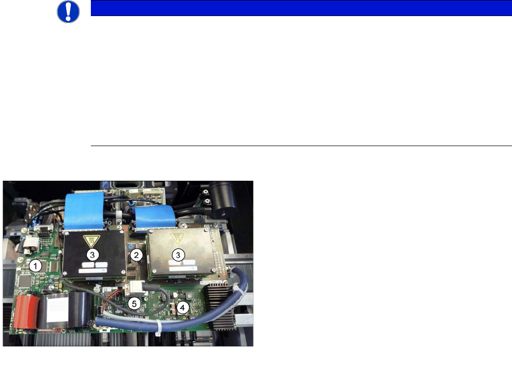
Boards on the gantry
Legend
1. Vision Board Spread Spectrum
2. Head adapter (here the version for the TwinHead with
2 HCUs)
3. HCU
4. Head interface
5. Sensor module
Installing the CPP Placement Head
Disassembling the TwinHead Conversion of the Head Adapter
60 Assembly Instructions / Montageanleitung Head Reconfiguration Kit CPP
Fitting the HCU onto the base adapter for CPP and C&P20A head
Installing the head adapter for CPP and C&P20A head
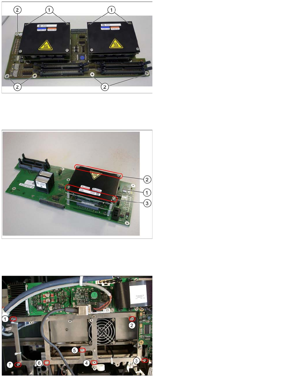
Head adapter of the TwinHead
► Loosen all electrical connections. You may want to
mark the position, to make clear assignment easier
later on.
► Loosen the two front screws (1) fastening the HCU in
each case. Make sure that you do not lose the shims.
Make a note of the number of shims used for each
screw, as this may well differ.
► Loosen all the screws (2) fastening the board and
then remove the board.
► Loosen both screws on the bottom side of the base
adapter to disconnect the HCU from the base adapt
-
er.
Fitting and fixing the HCU
► Carefully fit a HCU of the TwinHead onto the base
adapter of the parts set (1).
► Fix the HCU with the four previously removed screws
(2 and 3).
Mounting position for the head adapter
Legend
(1) - (7) Fastening bolts on the mounting position
Installing the CPP Placement Head
Preparing the Head for the Installation Height Assembly of the CPP Placement Head
Assembly Instructions / Montageanleitung Head Reconfiguration Kit CPP 61
Assembly of the CPP Placeme nt Head
3.4 Assembly of the CPP Placement Head
Preparing the Head for the Installation Heigh t
3.4.1 Preparing the Head for the Installation Height
Overview
Head adapter
Legend
(1) – (7) Fastening points on the head adapter
► Place the head adapter onto the fastening bolts in the
mounting position and fasten it with the 7 screws.
► Connect the head interface board via the plug con
-
nector with the head interface.
CAUTION
Installation instructions
► Check the firmware and perform a download, if needed.
CAUTION
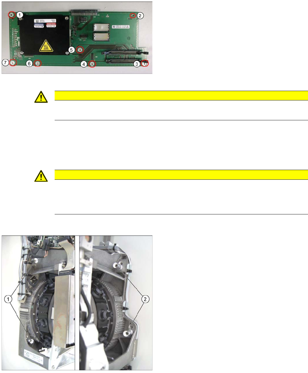
The placement head can be installed on two different heights. CPP_L corresponds to a com
-
ponent height of 6 mm. CPP_H corresponds to a component height of 11.5 mm.
If the CPP head is used in a placement area with stationary camera, TwinHead or WPC, it may
only be used in the upper position.
Legend
1. Fixing screws on the left side
2. Fixing screws on the right side
In this graphic the fixing screws are shown in the "head
top" position.