00196430-0102-AI_Head_Reconfiguration_Kit_SX_CPP_en_de.pdf - 第57页
Installing the CPP Placement Head Further Aspects for the Configuration Disassembling the C&P20A P lacement Head Assembly Instructions / Montageanleitung Head Reconfiguration K it CPP 57 See also 1.2 Preparatory Wo…
Installing the CPP Placement Head
Disassembling the C&P20A Placement Head Docking Out the Component Trolley and Switching Off the Machine
56 Assembly Instructions / Montageanleitung Head Reconfiguration Kit CPP
Disassembling the C&P20A Placement Head
3.2 Disassembling the C&P20A Placement Head
Parts, Equipment and Tools
▪ Torque screwdriver 100-500 Ncm [03078400-xx]
▪ Extension/straight TX20 [03073256-xx]
▪ Bit holder for Torque Vario-S screwdriver [03078706
-
xx]
Removal
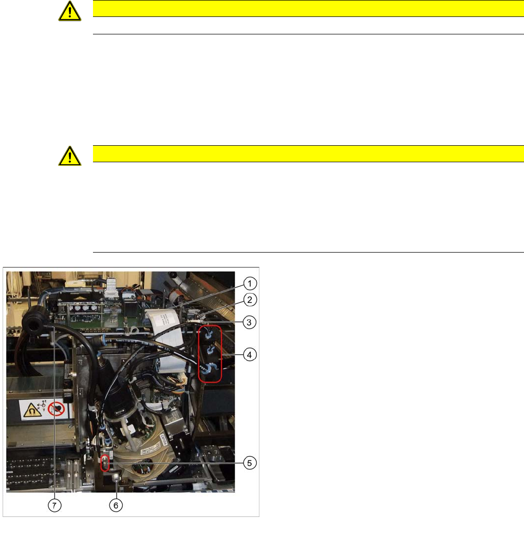
► Unplug the compressed air connections on the C&P20A at the positions (4) and (7).
► Disconnect the flat ribbon cable on the C&P20A (1).
► Loosen the screws fastening the strain reliefs on the component camera cables at the positions (2)
and (3) and carefully unplug the cables. While unplugging the cables, press the clamps on both sides
of the connectors.
One of the four head screws by means of which the C&P20A head is fixed to the head plate is located
behind the pressure control valve. The pressure control valve has to be swivelled to the left to gain ac
-
cess.
► Loosen the two screws on the pressure control valve (5).
► Loosen the undetachable screw (6) on the pressure control valve and swing the valve aside.
CAUTION
► You must wear the ESD armband during all work on the placement head.
CAUTION
Do not damage the component sensor prisms!
The component sensor prisms, underneath the placement head, are easily damaged. Take
great care when dismantling the head!
► Protect the component sensor with a piece of hose. This is delivered with the placement
head or component sensor and should be stored in the service box for the machine, as it is
required for dismantling the head.
Removing the C&P20A head
Legend
1. Flat ribbon cable
2. Strain relief component camera cable
3. Strain relief component camera cable
4. Compressed air connections
5. Screws on the pressure control valve
6. Undetachable screw on the pressure control valve
7. Discharged air hose to silencer
Installing the CPP Placement Head
Further Aspects for the Configuration Disassembling the C&P20A Placement Head
Assembly Instructions / Montageanleitung Head Reconfiguration Kit CPP 57
See also
1.2 Preparatory Work... [ ➙ 44]
Further Aspects for the Configurati on
3.2.1 Further Aspects for the Configuration
The following points have to be observed when replacing a C&P20A head by a CPP head:
▪ The existing head adapter can be kept.
▪ The C&P20A nozzle magazines are to be replaced by CPP nozzle magazines. The basic nozzle
changer body on SX machines is identical for both head types.
▪ The reject bin and the nozzle station can still be used.
Continue with section LINK.
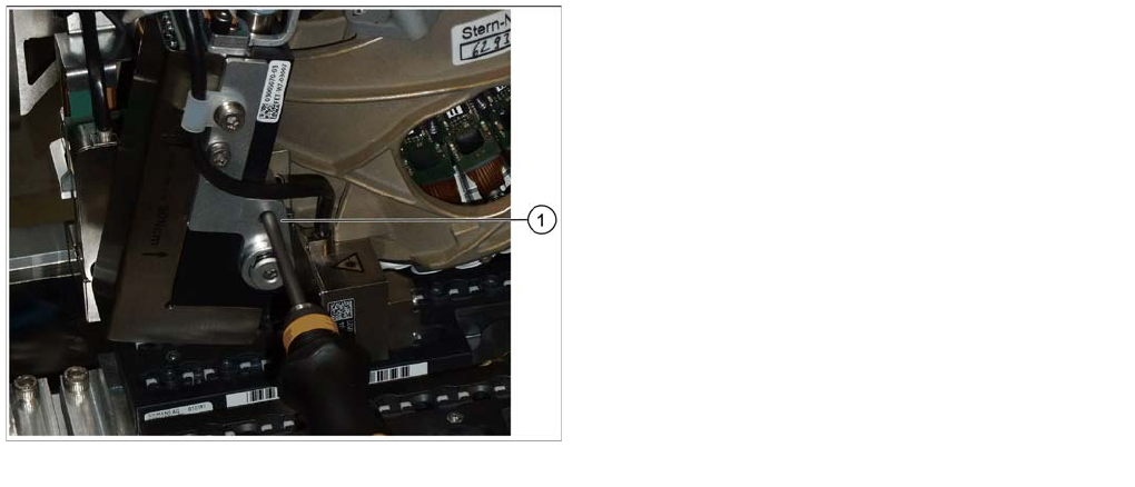
Removing the covered head screw
The covered head screw can now be accessed via a
guide drilling.
► Insert the Torx screwdriver into the guide drilling and
push it backwards until it sets down on the the head
screw.
► Loosen the covered head screw M4X14.
► Loosen the remaining three head screws M4x14 with
a long Torx screwdriver.
► The head is now freely suspended on a holder at the
gantry. Lift the head off the holder.
Installing the CPP Placement Head
Disassembling the TwinHead Further Aspects for the Configuration
58 Assembly Instructions / Montageanleitung Head Reconfiguration Kit CPP
Disassembling the TwinHead
3.3 Disassembling the TwinHead
The TwinHead consists of 2 identical Twin segments, which are fitted at an angle of 180° to one another.
When changing over to another placement head type both segments must be removed.
Parts, Equipment and Tools
▪ Torque screwdriver 100-500 Ncm [03078400-xx]
Removal
CAUTION
► You must wear the ESD armband during all work on the placement head.
NOTICE
The removal procedure is described here for module 1 (left). Repeat the procedure for
module 2 (right).
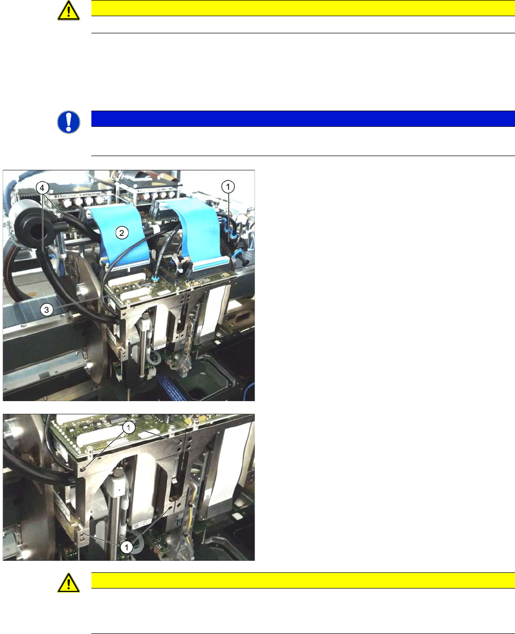
► Move the gantry into a position which allows you best
access.
► Unplug the pneumatic connection from the TwinHead
vacuum generator to the pneumatic distributor (1)
and the silencer.
► Remove both discharged air hoses from the silencer
(4).
► Unplug the pneumatic connection from the pneumat
-
ic distributor (1) to the TwinHead return cylinder.
► Unplug the flat ribbon cable (2) from the head main
board (3) on the TwinHead.
Each module is fixed with 4 screws to the head plate and
is positioned with two pins.
► Loosen the 4 M4x14 fixing screws (1) with a long Al
-
len key.
► Pull the module out of the locating pins.
► Remove module 2 the same way.
CAUTION
Removal instruction
The individual modules are not secured with a hook like it is the case for the C&P20A and the
CPP head. They can fall down.