00196430-0102-AI_Head_Reconfiguration_Kit_SX_CPP_en_de.pdf - 第63页
Installing the CPP Placement Head Fitting the Component Camera Assembly of the CPP Placement Head Assembly Instructions / Montageanleitung Head Reconfiguration K it CPP 63 Fitting t he Component Cam era 3.4.2 Fitting the…
Installing the CPP Placement Head
Assembly of the CPP Placement Head Preparing the Head for the Installation Height
62 Assembly Instructions / Montageanleitung Head Reconfiguration Kit CPP
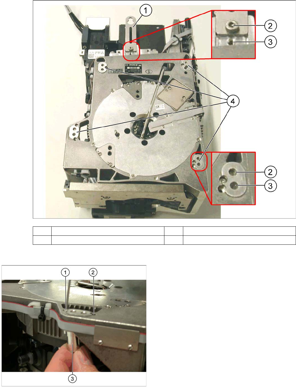
Conversion to another installation height
(1) Holding bracket (2) "Head bottom" position
(3) "Head top" position (4) Fixture holes with bushings
Legend
1. Drilling for the fixing screw of the bushing in "head
bottom" position
2. Drilling for the fixing screw of the bushing in "head
top" position
3. Bushing
All four bushings and the holding bracket must either be
fixed in top or bottom position.
Proceed as follows when replacing the bushings:
► Undo the fixing screws of the bushings.
► Insert the bushings in the correct position and re-
tighten them.
► Perform these steps for all four bushings and the
holding bracket of the head.
Installing the CPP Placement Head
Fitting the Component Camera Assembly of the CPP Placement Head
Assembly Instructions / Montageanleitung Head Reconfiguration Kit CPP 63
Fitting t he Component Camera
3.4.2 Fitting the Component Camera
The parts set does not include a component camera. The component camera must be ordered addition
-
ally.
Parts, Equipment and Tools
▪ Component camera [03018637-xx]
▪ Torque screwdriver 100-500 Ncm [03078400-xx]
▪ Extension/straight TX20 [03073256-xx]
▪ Bit holder for Torque Vario-S screwdriver [03078706-xx]
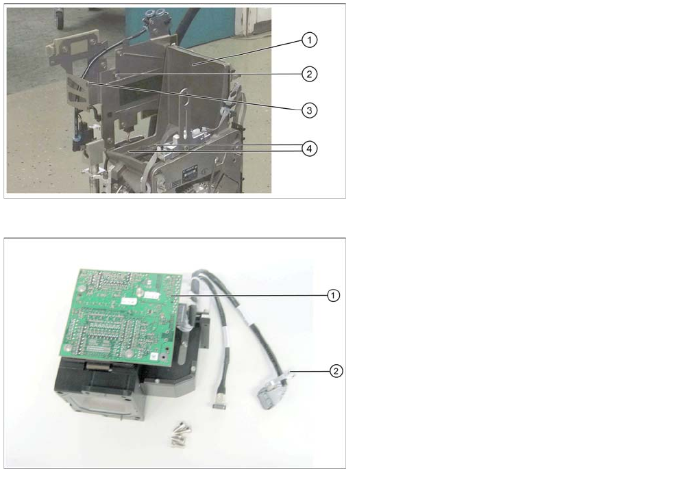
Overview
CPP head without component camera
Legend
1. Mounting position for the component camera
2. Fixing hole on the board holder
3. Fixing hole on the bracket
4. Fixing holes for the foot of the component camera
(two each on each side)
Component camera
Legend
1. Illumination control
2. Cable clamps
Installing the CPP Placement Head
Assembly of the CPP Placement Head Fitting the Component Camera
64 Assembly Instructions / Montageanleitung Head Reconfiguration Kit CPP
Installation
See also
2.3 Requirements and Restrictions for the CPP Placement Head [ ➙ 50]
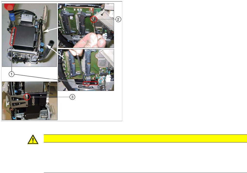
Installing the component camera
Legend
1. 4 screws at the foot of the camera DIN 912-M3 x 16-
A2-70 [00325349-xx]
2. Screw on the board holder ISO 4762 - M 2,5 x 4-A2-
70 [03042531-xx ] DIN 125-A 2.7-140HV-A2
[00201583-xx]
3. Screw on the retaining bracket ISO 4762 - M 2,5 x 4-
A2-70 [03042531-xx ] DIN 125-A 2.7-140HV-A2
[00201583-xx]
► Carefully place the component camera onto the locat
-
ing pins at the CPP head.
► Fasten the component camera to the CPP head with
four screws (1) and with one screw to the board hold
-
er (2).
► Fasten the component camera to the retaining brack
-
et (3).
CAUTION
Installation instructions
► Make sure that you do not damage or contaminate the camera optical system.
► Use a torque screwdriver for the component camera fixing screws. Tighten the 4 lower fix
-
ing screws with a torque of 145 Ncm.