D39489-BA-PM-EN.pdf - 第20页
20 D39489 | Date 12/2019 Diaphragm pump PJ25481 - 950.50.1 8 Tech nical D ata Translation of origina l Installat ion Instructions , english , KNF 125530 - 31 6634 06/18 9 Weight Pump type Value PJ25481 - 950.5 0.18 Appro…
19
D39489 | Date 12/2019
Technical Data Diaphragm pump PJ25481-950.50.18
8 Translation of original Installation Instructions, english, KNF 125530-316634 06/18
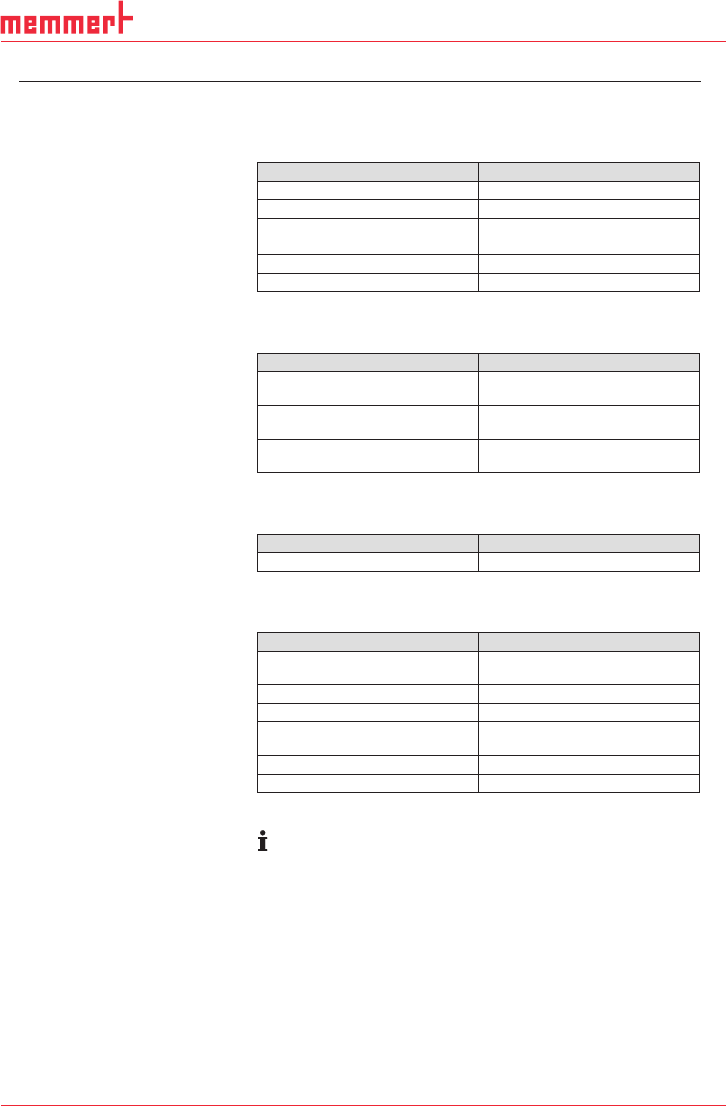
4. Technical Data
Pump materials
Assembly
Material
Diaphragm
PTFE coated
Valve plates
FFPM
O-ring
FPM (head 1-3)
FFPM (head 4)
Head plate
PPS
Intermediate plate
PPS
Tab. 2
Pneumatic values
Parameter
Value
Max. permissible operating
pressure [bar g]
-
Ultimate vacuum [mbar abs.]
with closed gas ballast
2.0
Delivery rate at atm. pressure
and 5V control voltage [l/min]*
55.0
Tab. 3 *Liters in standard state (1013 mbar)
Pneumatic Connections
Pump type
Value
PJ25481-950.50.18
Hose ID 10
Tab. 4
Electrical data
Parameter
Value
Automatic voltage selection
100-240 V
50 – 60 Hz
Max. current consumption [A]
1.9
Max. power consumption [W]
140
Maximum permitted mains
voltage fluctuations
± 10%
Protection class Motor
IP 20
Protection class Pump
IP 20
Tab. 5
The pump is supplied by a universal power supply with inte-
grated overload
protection.
They are protected against overheating by a temperature sen-
sor on the motor board and equipped with overcurrent protec-
tion.
If one of these safety functions is triggered, the pump will
be
shut down and must be manually reset, as follows:
Separate pump from mains.
Remove the cause(s) of the fault before restarting.
20
D39489 | Date 12/2019
Diaphragm pump PJ25481-950.50.18 Technical Data
Translation of original Installation Instructions, english, KNF 125530-316634 06/18 9
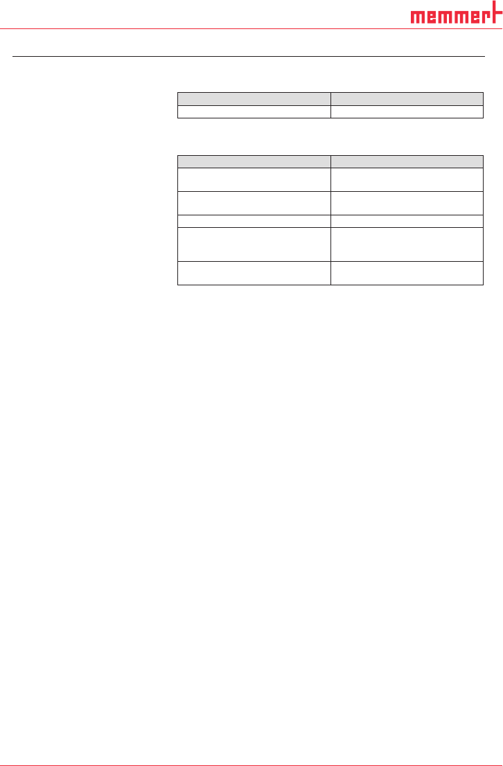
Weight
Pump type
Value
PJ25481-950.50.18
Approx. 7.2 kg
Tab. 6
Other parameters
Parameter
Value
Permissible ambient tempera-
ture
+ 10°C to + 40°C
Permissible media tempera-
ture
+ 5°C to + 40°C
Dimensions
See Fig. 3, Chapter 6.1
Maximum permissible ambient
relative humidity
80% for temperatures up to
31°C, decreasing linearly to
50% at 40°C.
Max. altitude of site:
[m above sea level]
2000
Tab. 7
21
D39489 | Date 12/2019
Design and function Diaphragm pump PJ25481-950.50.18
10 Translation of original Installation Instructions, english, KNF 125530-316634 06/18
5. Design and function
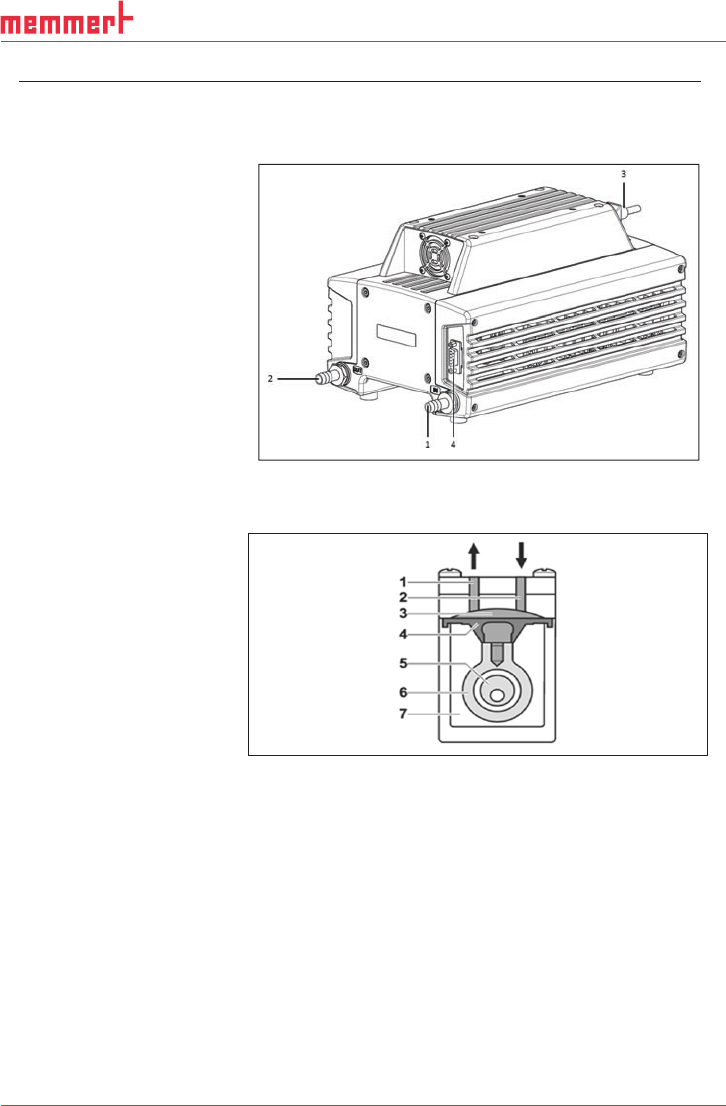
Design
Fig. 1: Design PJ25481-950.50.18
Function Diaphragm Pump
Fig. 2: Pump head
Diaphragm pumps transfer, compress (depending on pump ver-
sion) and evacuate gases and vapors.
The elastic diaphragm (4) is moved up and down by the eccentric
(5) and the connection rod (6). In the downward stroke it aspirates
the gas to be transferred via the inlet valve (2). In the upward
stroke, the diaphragm presses the medium out of the pump head
via the outlet valve (1). The transfer chamber (3) is hermetically
separated from the pump drive (7) by the diaphragm.
1 Inlet (suction side)
2 Outlet (pressure side)
3 Power switch, removable
mains cable
4 Sub-D-plug (motor control)
1 Outlet valve
2 Inlet valve
3 Transfer chamber
4 Diaphragm
5 Eccentric
6 Connection rod
7 Pump drive