D39489-BA-PM-EN.pdf - 第21页
21 D39489 | Date 12/2019 Design and f unction Diaphragm pump PJ25481 - 950.50.1 8 10 Translation of origina l Installat ion Instructions , english , KNF 125530 - 316634 06/ 18 5. Desi gn and function Design Fig. 1: Desig…
20
D39489 | Date 12/2019
Diaphragm pump PJ25481-950.50.18 Technical Data
Translation of original Installation Instructions, english, KNF 125530-316634 06/18 9
Weight
Pump type
Value
PJ25481-950.50.18
Approx. 7.2 kg
Tab. 6
Other parameters
Parameter
Value
Permissible ambient tempera-
ture
+ 10°C to + 40°C
Permissible media tempera-
ture
+ 5°C to + 40°C
Dimensions
See Fig. 3, Chapter 6.1
Maximum permissible ambient
relative humidity
80% for temperatures up to
31°C, decreasing linearly to
50% at 40°C.
Max. altitude of site:
[m above sea level]
2000
Tab. 7
21
D39489 | Date 12/2019
Design and function Diaphragm pump PJ25481-950.50.18
10 Translation of original Installation Instructions, english, KNF 125530-316634 06/18
5. Design and function
Design
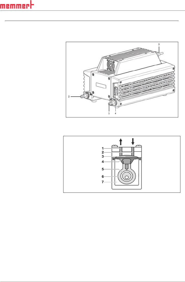
Fig. 1: Design PJ25481-950.50.18
Function Diaphragm Pump
Fig. 2: Pump head
Diaphragm pumps transfer, compress (depending on pump ver-
sion) and evacuate gases and vapors.
The elastic diaphragm (4) is moved up and down by the eccentric
(5) and the connection rod (6). In the downward stroke it aspirates
the gas to be transferred via the inlet valve (2). In the upward
stroke, the diaphragm presses the medium out of the pump head
via the outlet valve (1). The transfer chamber (3) is hermetically
separated from the pump drive (7) by the diaphragm.
1 Inlet (suction side)
2 Outlet (pressure side)
3 Power switch, removable
mains cable
4 Sub-D-plug (motor control)
1 Outlet valve
2 Inlet valve
3 Transfer chamber
4 Diaphragm
5 Eccentric
6 Connection rod
7 Pump drive
22
D39489 | Date 12/2019
Diaphragm pump PJ25481-950.50.18 Installation and connection
Translation of original Installation Instructions, english, KNF 125530-316634 06/18 11
6. Installation and connection
Only install and operate the pumps under the pneumatic operating
parameters and conditions described in Chapter 4, Technical Data.
Observe the safety precautions (see Chapter 3).
6.1. Installation of the pump
Choose a safe location (flat surface) for the pump.
Before installation, store the pump at the installation location to
bring it up to ambient temperature.
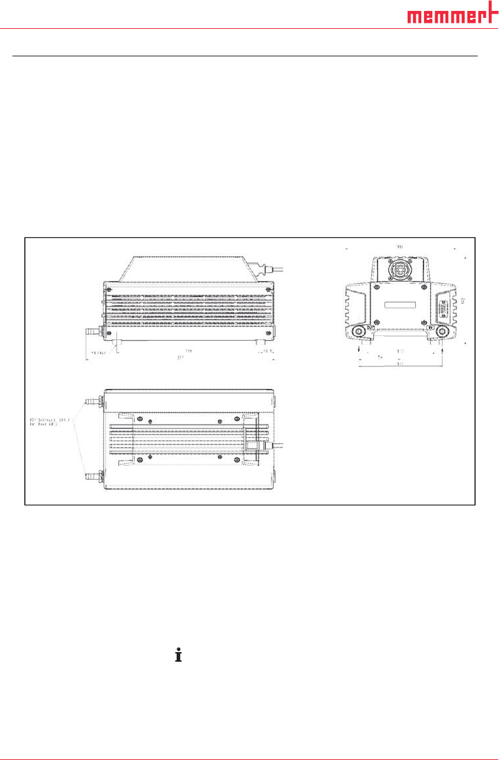
See Fig. 3 for mounting dimensions.
Fig. 3: Mounting dimensions PJ25481-950.50.18 (All dimensional toler-
ances conform to DIN ISO 2768-1, Tolerance Class V)
Install the pump so that the motor fan can intake sufficient
cooling air.
Make sure that the installation location is dry and the pump is
protected against rain, splash, hose and drip water as well as
other pollutions.
Make sure, that the installation location is accessible for
maintenance and service.
The IP protection class of the pump motor is indicated on the
type plate.
Install the pump at the highest point in the system to prevent
condensate from collecting in the pump head.
Protect the pump from dust.
Mounting dimensions
Cooling air supply
Installation location