D39489-BA-PM-EN.pdf - 第35页
35 D39489 | Date 12/2019 Servicin g Diaphragm pump PJ25481 - 950.50.1 8 24 Translation of original Inst allation Inst ructions , e nglish , KNF 125530 - 31 6634 06/18 8. Head 4 ( Fig. 6/ I III ): Use a felt - tip p en to…
34
D39489 | Date 12/2019
Diaphragm pump PJ25481-950.50.18 Servicing
Translation of original Installation Instructions, english, KNF 125530-316634 06/18 23
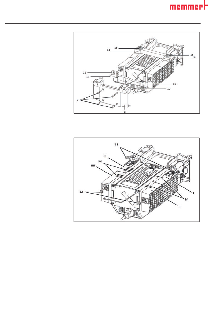
Fig. 5: Disassembling the head connections
4. Remove O-rings (Fig. 6/12) and flat seals (13).
Fig. 6: Marking the pump
5. Head 1 (Fig. 6/I):
Use a felt-tip pen to apply a single mark (M) to the head plate,
intermediate plate, and compressor housing.
6. Head 2 (Fig. 6/II):
Use a felt-tip pen to apply two marks (M) to the head plate, in-
termediate plate, and compressor housing.
7. Head 3 (Fig. 6/III):
Use a felt-tip pen to apply three marks (M) to the head plate,
intermediate plate, and compressor housing.
35
D39489 | Date 12/2019
Servicing Diaphragm pump PJ25481-950.50.18
24 Translation of original Installation Instructions, english, KNF 125530-316634 06/18
8. Head 4 (Fig. 6/IIII):
Use a felt-tip pen to apply four marks (M) to the head plate, in-
termediate plate, and compressor housing.
During re-assembly, refer to the marks on the individual heads
to ensure th
at the parts are properly re-assembled.
9. Undo the 16 attachment screws (Fig. 4/3) on the heads (1 to 4)
and remove the heads (1 and 2 as well as 3 and 4).
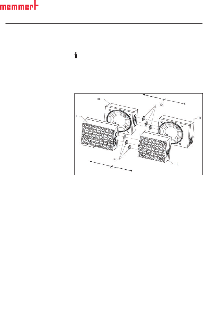
10. Pull apart heads 1 (Fig. 7/I) and 2 (II) and heads 3 (III) and 4
(IIII) and remove O-rings (19).
Fig. 7: Removing the o-rings
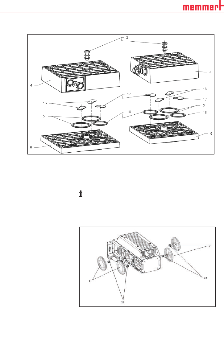
11. On all four heads, undo the head screw (Fig. 8/2) in the head
plate (4) and remove head plate from the intermediate plate
(6).
36
D39489 | Date 12/2019
Diaphragm pump PJ25481-950.50.18 Servicing
Translation of original Installation Instructions, english, KNF 125530-316634 06/18 25
Fig. 8: Exploded drawing of pump heads 1 and 2
Replacing the diaphragms and valve plates
1. Manually remove the four diaphragms (Fig. 9/7) by turning
them in the counterclockwise direction.
Use caution to prevent the diaphragm spacers (21) located be-
tween the diaphragm and the connecting rod from falling into
the pump housing. The diaphragm and the connecting rod from
falling into the housing. The diaphragm spacers (
21) must be
installed in the same quantity as before in order to ensure th
e
pump’s pneumatic performance.
Fig. 9: Replacing diaphragm