D39489-BA-PM-EN.pdf - 第39页
39 D39489 | Date 12/2019 Diaphragm pump PJ25481 - 950.50.1 8 Servicing Translation of origina l Installat ion Instructions , english , KNF 125530 - 31 6634 06/18 27 Final steps 1. Reconnect suctio n and pres sure line on…
38
D39489 | Date 12/2019
Servicing Diaphragm pump PJ25481-950.50.18
26 Translation of original Installation Instructions, english, KNF 125530-316634 06/18
2. Remove from the intermediate plates (Fig. 8/6) the valve plates
(16) and (17) and the O-rings (5) and (18).
3. Manually screw the ne diaphragms (Fig. 9/7) into the connect-
ing rod’s threads and tighten to hand tightness.
Before you finally tighten the diaphragms, you are recom-
mended to move the diaphragm to the upper dead center.
4. Insert the new valve plates (Fig. 8/16) and (17) and the new O-
rings (5) and (18) into the intermediate plates (6).
The upper and lower sides of the valve plates are identical.
When inserting the O-rings, make sure that they are the correct
size and color (head 4: black O
-rings).
Install intermediate plates and head cover
1. Place head plate (Fig. 8/4) onto the intermediate plates (6), ob-
serving the felt-tip pen marks (Fig. 6/M).
2. With your hands, carefully and lightly tighten the head plate’s
head screw (Fig. 8/2) on all four heads (tightening torque:
60 Ncm).
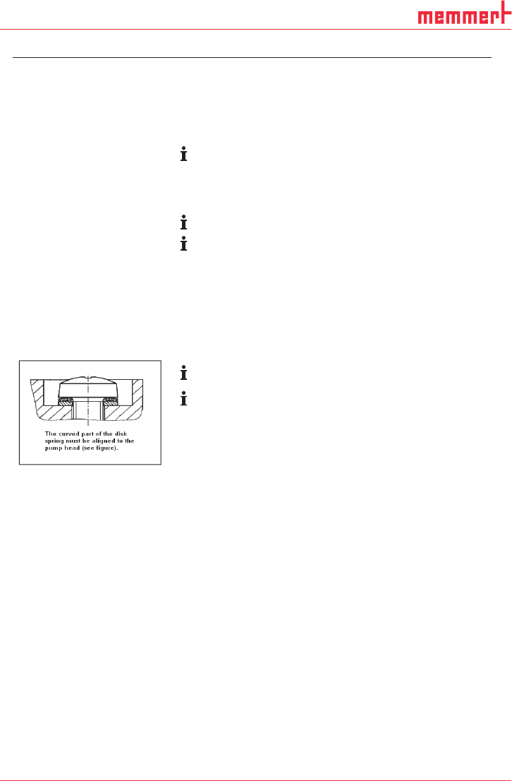
Refer to for arrangement and alignment of disk springs and the
screw’s washer.
When inserting the O-rings, make sure that they are the correct
size and color (head 4: black O
-rings).
3. Place three O-rings (Fig. 7/19) into each of the head connec-
tion holes.
4. Press together heads 1 and 2 (Fig. 6/I and II) and heads 3 and
4 (III and IIII).
5. Place heads 1 and 2 and heads 3 and 4 onto the compressor
housing; alternately tighten attachment screws (Fig. 4/3) to
hand-tightness (tightening torque: 3.5 Nm).
6. Insert O-rings (Fig. 6/12) and flat seals (13) into the head con-
nection receiver.
7. Reinstall the head connections:
To do this, manually tighten the head connections’ attachment
screws (Fig. 5/10 and 15).
8. Reinstall the head connection cover (8):
To do this, manually tighten the head connection cover’s at-
tachment screws (9).
9. Reinstall the head covers (Fig. 4/20):
To do this, manually tighten the eight attachment screws (1).
10. Properly dispose of the old diaphragms, valve plates, and O-
rings.
Fig. 10: Aligning the
disk spring

39
D39489 | Date 12/2019
Diaphragm pump PJ25481-950.50.18 Servicing
Translation of original Installation Instructions, english, KNF 125530-316634 06/18 27
Final steps
1. Reconnect suction and pressure line on the pump.
2. Reconnect the pump to the mains.
If you have any questions about servicing, call your KNF technical
adviser (contact data: see www.knf.com).
40
D39489 | Date 12/2019
Troubleshooting Diaphragm pump PJ25481-950.50.18
28 Translation of original Installation Instructions, english, KNF 125530-316634 06/18
9. Troubleshooting
DANGER
Extreme danger from electrical shock!
Disconnect the pump power supply before work-
ing on the pump.
Make sure the pump is de-energized and se-
cure.
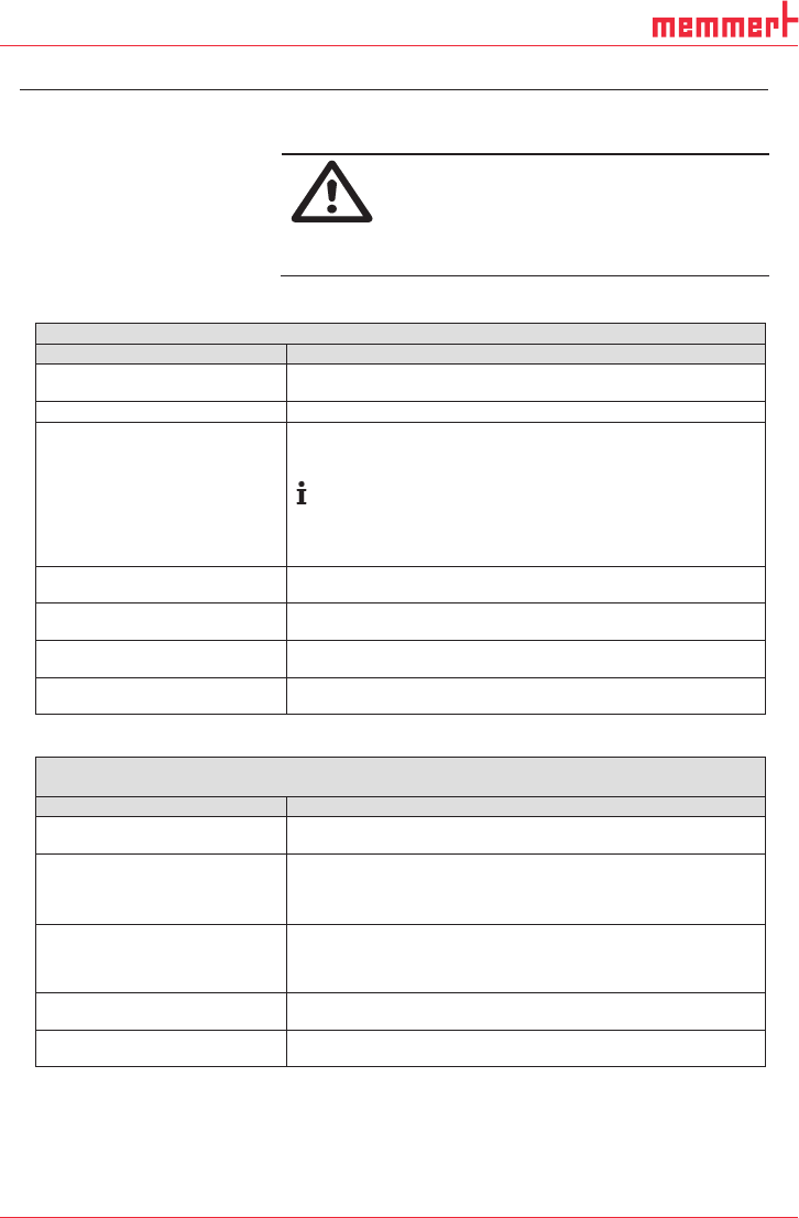
Check the pump (see Tab. 12 and Tab. 13).
Pump does not transfer
Cause
Fault remedy
Pump not connected to the
mains.
Connect pump to the mains.
No voltage in the mains.
Check room fuse and switch on if necessary.
The motor board’s overcur-
rent protection circuit has
activated.
Maximum temperature of
motor board is exceeded.
Maximum blocking time of
the rotor is exceeded.
Separate pump from the mains.
Determine and remove the cause of the overcurrent (for ex-
ample: improper pressure, liquid in the pump heads).
The pump must be separated from the mains for several
seconds before the electronics will permit restarting.
Connections or hoses are
blocked.
Check hoses and connections.
Remove blockage.
External valve is closed or filter
is clogged.
Check external valves and filters.
Condensate has collected in the
pump head.
Detach the condensate source from the pump.
Flush the pump (see Chapter 8.2.1).
Diaphragm or valve plates are
worn.
Replace diaphragm and valve plates (see Chapter 8.3).
Tab. 12
Flow rate, pressure or vacuum too low
The pump does not achieve the output specified in the Technical data or the data sheet.
Cause
Fault remedy
Condensate has collected in the
pump head.
Detach the condensate source from the pump.
Flush the pump (see Chapter 8.2.1).
Presence of positive pressure
on the pressure side with simul-
taneous vacuum or positive
pressure on the suction side.
Change the pressure conditions.
Cross-section of pneumatic
hoses or connectors too narrow
or restricted.
Disconnect the pump from system and determine output
values.
Remove restriction (e.g. valve) if necessary.
If applicable, use larger-diameter hoses or connectors.
Leaks in connections, hoses or
pump head.
Make sure the hoses and connections.
Remove any parts or particles causing blockages.
Pump head components are
soiled.
Clean head components.