D39489-BA-PM-EN.pdf - 第33页
33 D39489 | Date 12/2019 Servicin g Diaphragm pump PJ25481 - 950.50.1 8 22 Trans lation of orig inal Instal lation Instructi ons , englis h , KNF 1255 30 - 316634 0 6/18 Fig . 4: Exploded draw ing PJ254 81 - 950.50.18 1 …
32
D39489 | Date 12/2019
Diaphragm pump PJ25481-950.50.18 Servicing
Translation of original Installation Instructions, english, KNF 125530-316634 06/18 21
8.3. Replacing diaphragm and reed valves
Pump disconnected from mains and de-energized
Pump is clean and free of hazardous materials.
Hoses removed from pump’s pneumatic inlet and outlet.
Spare part/tool
Spare parts set according to spare parts list, Chapter 10
Allen key 2-mm (hexagon)
Phillips screwdriver No. 2
Allen key 4-mm (hexagon)
Felt-tip pen
Tab. 11
Always replace diaphragm and valve plates together to main-
tain the pump performance.
WARNING
Dangerous substances in the pump can cause a
health hazard.
Depending on the substance transferred, caustic
burns or poisoning are possible.
Wear protective clothing if necessary, e.g. pro-
tective gloves.
Flush the pump before replacing the diaphragm
and valve plates (see Chapter 8.2.1).
CAUTION
Danger of burns from hot pump parts
The pump head or motor may be
hot even after the
pump has been shut off.
Allow the pump to cool off after operation.
Requirements
Spare parts/tools
Information on procedure
33
D39489 | Date 12/2019
Servicing Diaphragm pump PJ25481-950.50.18
22 Translation of original Installation Instructions, english, KNF 125530-316634 06/18
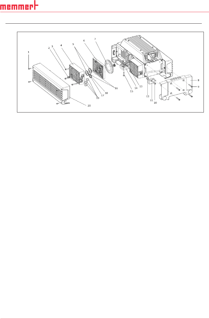
Fig. 4: Exploded drawing PJ25481-950.50.18
1 8x attachment screws
(head cover)
2
4x head screws
3
16x attachment screws
(head)
4
4x head plates
5
8x O-rings (ø24 x 2)
6
4x intermediate plates
7
4x diaphragms
8
1x connection cover
9
4x attachment screws
(connection cover)
10
2x attachment screws
(connection .50)
11 2x connection blocks .50
12
2x O-rings (ø7,65 x1,78)
13
2x flat seals
14
2x connection blocks .1.2
15
2x attachment screws
(connection .1.2)
16
8x valve plates
17
6x valve plates
18
6x O-rings (ø18,77 x
1,78)
19
6x O-rings (ø10 x 2,5)
20
2x head covers
Removing the pump head
1. Undo the eight screws (Fig. 4/1) and remove the head covers
(20).
2. Undo the connection cover’s (8) attachment screws (Fig. 5/9)
and remove the connection cover.
3. Remove the head connection’s (11) and (14) screws (10) and
(15) and remove the head connections.
34
D39489 | Date 12/2019
Diaphragm pump PJ25481-950.50.18 Servicing
Translation of original Installation Instructions, english, KNF 125530-316634 06/18 23
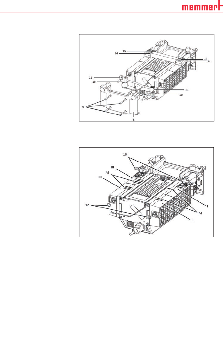
Fig. 5: Disassembling the head connections
4. Remove O-rings (Fig. 6/12) and flat seals (13).
Fig. 6: Marking the pump
5. Head 1 (Fig. 6/I):
Use a felt-tip pen to apply a single mark (M) to the head plate,
intermediate plate, and compressor housing.
6. Head 2 (Fig. 6/II):
Use a felt-tip pen to apply two marks (M) to the head plate, in-
termediate plate, and compressor housing.
7. Head 3 (Fig. 6/III):
Use a felt-tip pen to apply three marks (M) to the head plate,
intermediate plate, and compressor housing.