D39489-BA-PM-EN.pdf - 第38页
38 D39489 | Date 12/2019 Servicin g Diap hragm pum p PJ25481 - 950.50.18 26 T ranslation of or iginal Inst allation Instruc tions , e nglish , KNF 1 25530 - 31663 4 06/18 2. Remove from the interm ediate plates ( Fig. 8/…
37
D39489 | Date 12/2019
Servicing Diaphragm pump PJ25481-950.50.18
26 Translation of original Installation Instructions, english, KNF 125530-316634 06/18
2. Remove from the intermediate plates (Fig. 8/6) the valve plates
(16) and (17) and the O-rings (5) and (18).
3. Manually screw the ne diaphragms (Fig. 9/7) into the connect-
ing rod’s threads and tighten to hand tightness.
Before you finally tighten the diaphragms, you are recom-
mended to move the diaphragm to the upper dead center.
4. Insert the new valve plates (Fig. 8/16) and (17) and the new O-
rings (5) and (18) into the intermediate plates (6).
The upper and lower sides of the valve plates are identical.
When inserting the O-rings, make sure that they are the correct
size and color (head 4: black O
-rings).
Install intermediate plates and head cover
1. Place head plate (Fig. 8/4) onto the intermediate plates (6), ob-
serving the felt-tip pen marks (Fig. 6/M).
2. With your hands, carefully and lightly tighten the head plate’s
head screw (Fig. 8/2) on all four heads (tightening torque:
60 Ncm).
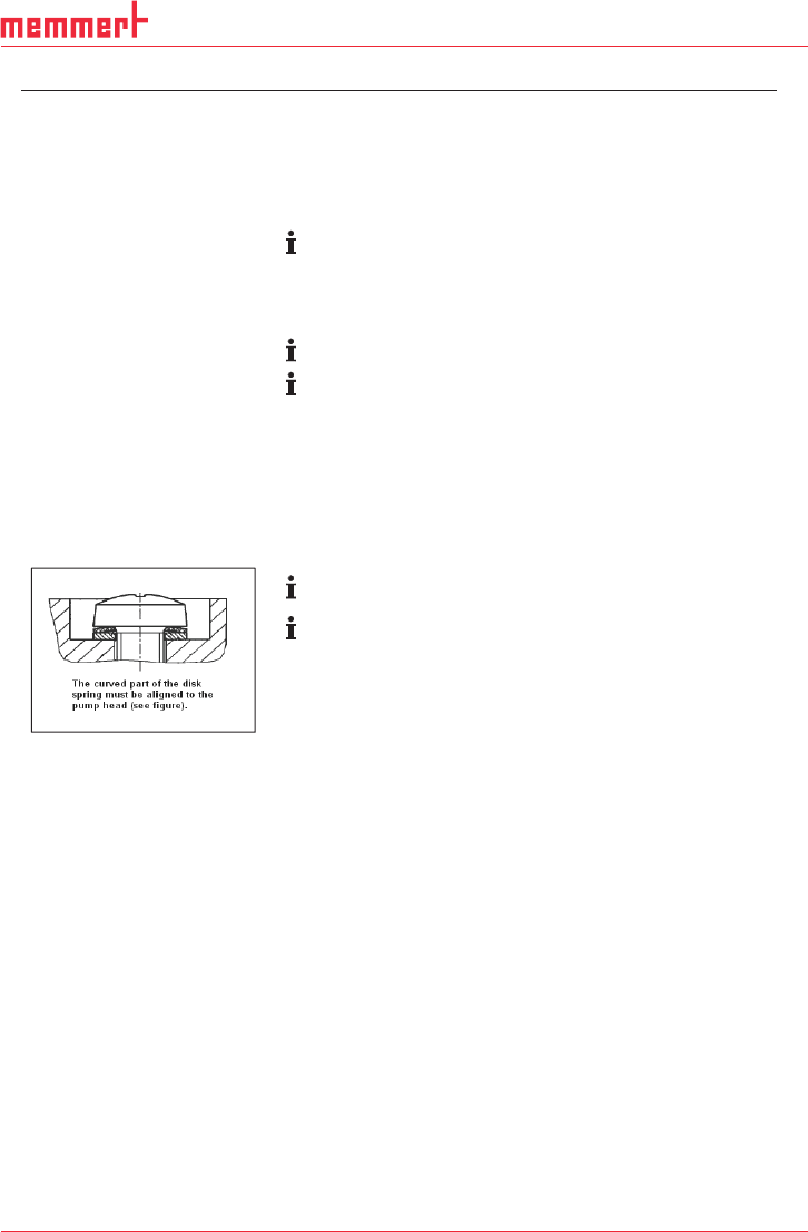
Refer to for arrangement and alignment of disk springs and the
screw’s washer.
When inserting the O-rings, make sure that they are the correct
size and color (head 4: black O
-rings).
3. Place three O-rings (Fig. 7/19) into each of the head connec-
tion holes.
4. Press together heads 1 and 2 (Fig. 6/I and II) and heads 3 and
4 (III and IIII).
5. Place heads 1 and 2 and heads 3 and 4 onto the compressor
housing; alternately tighten attachment screws (Fig. 4/3) to
hand-tightness (tightening torque: 3.5 Nm).
6. Insert O-rings (Fig. 6/12) and flat seals (13) into the head con-
nection receiver.
7. Reinstall the head connections:
To do this, manually tighten the head connections’ attachment
screws (Fig. 5/10 and 15).
8. Reinstall the head connection cover (8):
To do this, manually tighten the head connection cover’s at-
tachment screws (9).
9. Reinstall the head covers (Fig. 4/20):
To do this, manually tighten the eight attachment screws (1).
10. Properly dispose of the old diaphragms, valve plates, and O-
rings.
Fig. 10: Aligning the
disk spring
38
D39489 | Date 12/2019
Servicing Diaphragm pump PJ25481-950.50.18
26 Translation of original Installation Instructions, english, KNF 125530-316634 06/18
2. Remove from the intermediate plates (Fig. 8/6) the valve plates
(16) and (17) and the O-rings (5) and (18).
3. Manually screw the ne diaphragms (Fig. 9/7) into the connect-
ing rod’s threads and tighten to hand tightness.
Before you finally tighten the diaphragms, you are recom-
mended to move the diaphragm to the upper dead center.
4. Insert the new valve plates (Fig. 8/16) and (17) and the new O-
rings (5) and (18) into the intermediate plates (6).
The upper and lower sides of the valve plates are identical.
When inserting the O-rings, make sure that they are the correct
size and color (head 4: black O
-rings).
Install intermediate plates and head cover
1. Place head plate (Fig. 8/4) onto the intermediate plates (6), ob-
serving the felt-tip pen marks (Fig. 6/M).
2. With your hands, carefully and lightly tighten the head plate’s
head screw (Fig. 8/2) on all four heads (tightening torque:
60 Ncm).
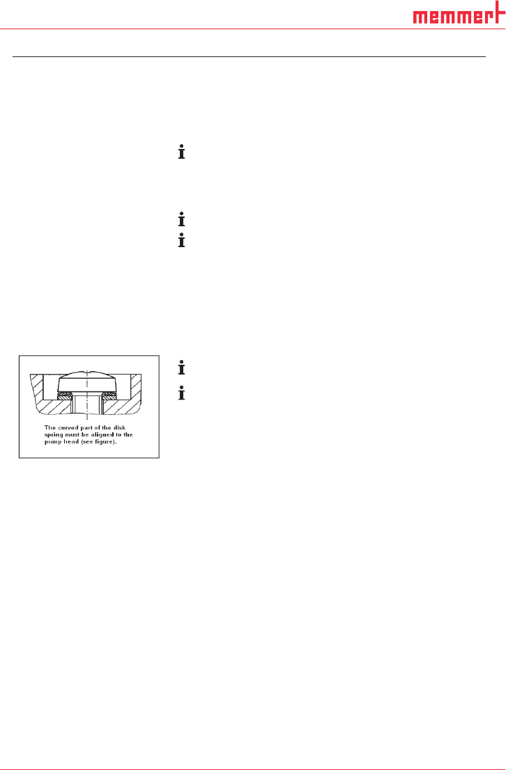
Refer to for arrangement and alignment of disk springs and the
screw’s washer.
When inserting the O-rings, make sure that they are the correct
size and color (head 4: black O
-rings).
3. Place three O-rings (Fig. 7/19) into each of the head connec-
tion holes.
4. Press together heads 1 and 2 (Fig. 6/I and II) and heads 3 and
4 (III and IIII).
5. Place heads 1 and 2 and heads 3 and 4 onto the compressor
housing; alternately tighten attachment screws (Fig. 4/3) to
hand-tightness (tightening torque: 3.5 Nm).
6. Insert O-rings (Fig. 6/12) and flat seals (13) into the head con-
nection receiver.
7. Reinstall the head connections:
To do this, manually tighten the head connections’ attachment
screws (Fig. 5/10 and 15).
8. Reinstall the head connection cover (8):
To do this, manually tighten the head connection cover’s at-
tachment screws (9).
9. Reinstall the head covers (Fig. 4/20):
To do this, manually tighten the eight attachment screws (1).
10. Properly dispose of the old diaphragms, valve plates, and O-
rings.
Fig. 10: Aligning the
disk spring

39
D39489 | Date 12/2019
Diaphragm pump PJ25481-950.50.18 Servicing
Translation of original Installation Instructions, english, KNF 125530-316634 06/18 27
Final steps
1. Reconnect suction and pressure line on the pump.
2. Reconnect the pump to the mains.
If you have any questions about servicing, call your KNF technical
adviser (contact data: see www.knf.com).