D39489-BA-PM-EN.pdf - 第27页
27 D39489 | Date 12/2019 Operation Diaphr agm pum p PJ25481 - 950.50.18 16 Trans lation of orig inal Instal lation Instructi ons , englis h , KNF 1255 30 - 316634 0 6/18 W ARN I NG Hazard of the pump hea d bursting due t…
26
D39489 | Date 12/2019
Diaphragm pump PJ25481-950.50.18 Operation
Translation of original Installation Instructions, english, KNF 125530-316634 06/18 15
7. Operation
7.1. Initial start-up
Operational requirements
Pump
All hoses attached properly.
Fan openings not blocked.
Specifications of the power supply corre-
spond with the data on the pump’s type plate.
Ensure that the pump outlet is not closed or
constricted.
Tab. 8
7.2. Start up
WARNING
Danger of burns from hot pump parts or hot medium
During or after operation of the pump, some pump
parts may be hot.
Allow the pump to cool after operation.
Take safety precautions against the contact of
hot parts/media.
WARNING
Injury of the eyes
During excessive approach to the inlet or outlet of
the pump, the eyes could be injured by the upcoming
vacuum or overpressure.
Don’t look into the pump’s inlet or outlet during
the operation.
Only operate the pumps under the operating parameters and
conditions described in Chapter 4. Technical Data.
Make sure the pumps are used properly (see Chapter 2.1).
Make sure the pumps are not used improperly (see Chapter
2.2).
Observe the safety precautions (see Chapter 3).
27
D39489 | Date 12/2019
Operation Diaphragm pump PJ25481-950.50.18
16 Translation of original Installation Instructions, english, KNF 125530-316634 06/18
WARNING
Hazard of the pump head bursting due to excessive
pressure increase
Do not exceed max. permissible operating pres-
sure (see Chapter 4. Technical Data.
Monitor pressure during operation.
If the pressure exceeds the maximum permissi-
ble operating pressure, immediately switch off
pump and eliminate fault (see Chapter
9. Trou-
bleshooting).
Only throttle or regulate the air or gas quantity in
the suction line to prevent the maximum permis-
sible operating pressure from being exceeded.
If the air or gas quantity in the pressure line is
throttled or regulated, make sure that the maxi-
mum permissible operating pressure is not ex-
ceeded.
Ensure that the pump outlet is not closed or con-
stricted.
Excessive pressure (with all of the related hazards) can be pre-
vented by placing a bypass line with a pressure
-relief valve be-
tween the pressure and suctions sides of the pump. For further
information, contact our technical adviser (contact data: see
www.k
nf.com).
With the pump at a standstill, open pressure and suction lines to
normal atmospheric pressure.
WARNING
Automatic starting can cause personal injury and
pump damage
When the operation of the pump is interrupted by the
thermal
switch or the trigging device for PTC sen-
sors, the pump will restart automatically after cooling
down.
Take all necessary care to prevent this leading
to a dangerous situation.
7.3. Switching Pump on/off
Switching pump on
The pump may not start up against pressure during switch-on.
This also applies in operating following a brief power failure.
If
a
pump starts against pressure, it may block.
This activates the
overload switch and the pump switches off.
Make sure that normal atmospheric pressure is present in the
lines during switch-on.
Pumpe am Netzschalter einschalten (siehe Fig. 1/3 in Kapitel
5).
Depending on the applied electrical voltage, initialization of the
electronics may take up to one second before the pump starts.
Pump standstill
28
D39489 | Date 12/2019
Diaphragm pump PJ25481-950.50.18 Operation
Translation of original Installation Instructions, english, KNF 125530-316634 06/18 17
External actuation
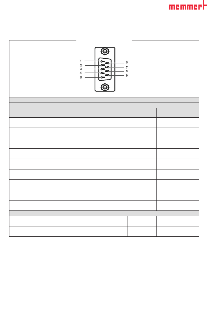
Elektrische Anschlüsse / Electrical connection
Litzenbelegung / lead assignment
Pin Nr. Funktion / function
Signalname
signal name
1
5V Ausgangsspannung
5V power supply
U
5V
2
Masse
Ground
GND
3
Masse
Ground
GND
4
Ausgangssignal Drehzahl
Output signal speed
U
Spd
5
Versorgung Gasballastventil
Supply gas ballast valve
U
+GB
6
Eingangssignal Drehzahlregelung
Input signal speed control
U
Ctrl
7
Ausgangssignal Fehler
Output signal fault
U
Flt
8
Eingangssignal Remote EIN/AUS
Input signal Remote ON/OFF
U
Rmt
9
Masse Gasballastventil
Ground gas ballast valve
U
-GB
5V Ausgangsspannung U
5V
/ 5V Power supply U
5V
Ausgangsspannung DC
Output voltage range DC
[V] 5 ± 0.2
Max. Ausgangsstrom
Max. current output
[mA] 170
Tab. 9 (part 1): Connection plan motor electronics