D39489-BA-PM-EN.pdf - 第40页
40 D39489 | Date 12/2019 Troubleshoot ing Diaphragm pump PJ25481 - 950.50.1 8 28 Trans lation of orig inal Instal lation Instructi ons , englis h , KNF 1255 30 - 316634 0 6/18 9. Troubl eshooting DAN G E R Extreme danger…
39
D39489 | Date 12/2019
Diaphragm pump PJ25481-950.50.18 Servicing
Translation of original Installation Instructions, english, KNF 125530-316634 06/18 27
Final steps
1. Reconnect suction and pressure line on the pump.
2. Reconnect the pump to the mains.
If you have any questions about servicing, call your KNF technical
adviser (contact data: see www.knf.com).
40
D39489 | Date 12/2019
Troubleshooting Diaphragm pump PJ25481-950.50.18
28 Translation of original Installation Instructions, english, KNF 125530-316634 06/18
9. Troubleshooting
DANGER
Extreme danger from electrical shock!
Disconnect the pump power supply before work-
ing on the pump.
Make sure the pump is de-energized and se-
cure.
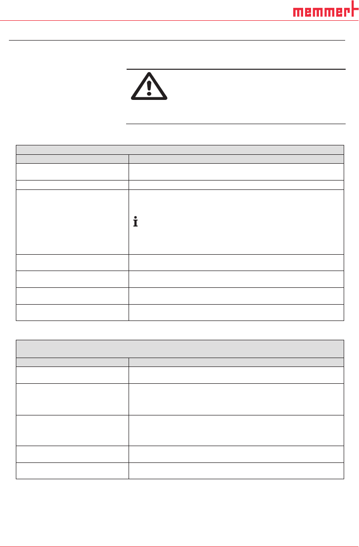
Check the pump (see Tab. 12 and Tab. 13).
Pump does not transfer
Cause
Fault remedy
Pump not connected to the
mains.
Connect pump to the mains.
No voltage in the mains.
Check room fuse and switch on if necessary.
The motor board’s overcur-
rent protection circuit has
activated.
Maximum temperature of
motor board is exceeded.
Maximum blocking time of
the rotor is exceeded.
Separate pump from the mains.
Determine and remove the cause of the overcurrent (for ex-
ample: improper pressure, liquid in the pump heads).
The pump must be separated from the mains for several
seconds before the electronics will permit restarting.
Connections or hoses are
blocked.
Check hoses and connections.
Remove blockage.
External valve is closed or filter
is clogged.
Check external valves and filters.
Condensate has collected in the
pump head.
Detach the condensate source from the pump.
Flush the pump (see Chapter 8.2.1).
Diaphragm or valve plates are
worn.
Replace diaphragm and valve plates (see Chapter 8.3).
Tab. 12
Flow rate, pressure or vacuum too low
The pump does not achieve the output specified in the Technical data or the data sheet.
Cause
Fault remedy
Condensate has collected in the
pump head.
Detach the condensate source from the pump.
Flush the pump (see Chapter 8.2.1).
Presence of positive pressure
on the pressure side with simul-
taneous vacuum or positive
pressure on the suction side.
Change the pressure conditions.
Cross-section of pneumatic
hoses or connectors too narrow
or restricted.
Disconnect the pump from system and determine output
values.
Remove restriction (e.g. valve) if necessary.
If applicable, use larger-diameter hoses or connectors.
Leaks in connections, hoses or
pump head.
Make sure the hoses and connections.
Remove any parts or particles causing blockages.
Pump head components are
soiled.
Clean head components.
41
D39489 | Date 12/2019
Diaphragm pump PJ25481-950.50.18 Troubleshooting
Translation of original Installation Instructions, english, KNF 125530-316634 06/18 29
Pump head components are
soiled.
Clean head components.
Diaphragm or valves plates are
worn.
Replace diaphragm and valve plates (see Chapter 8.3).
Diaphragm and valve plates
have been replaced.
Make sure that the shim rings have been replaced onto the
diaphragm screw thread.
Check head connection and hose connections for leaks.
Tab. 13
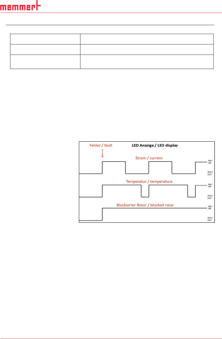
Fault visualization on motor controller
The excess of the overcurrent limit, the excess of the maximum
temperature of the motor board or the blocking of the rotor is
shown as a fault. A red LED on the BLDC motor controller signals
the cause of the fault.
Optional settings:
If desired, the motor controller can be programmed so that the er-
ror output voltage exhibits the same characteristics as the LED.
With factory settings, only 1 or 0 are logically outputted as voltage
at the fault output.
Fig. 11: LED blinking duration according to different faults
To delete the error condition the motor has to be disconnected
from the mains.
Fault cannot be rectified
If you are unable to identify the cause of the problem, please send
the pump to KNF customer services (contact data: see
www.knf.com).
1. Flush the pump (see Chapter 8.2.1).
2. Clean the pump (see Chapter 8.2.2).
3. Send the pump, together with completed Health and Safety
Clearance and Decontamination Form (Chapter 12), to KNF
stating the nature of the transferred medium.