D39489-BA-PM-EN.pdf - 第31页
31 D39489 | Date 12/2019 Servicin g Diaphragm pump PJ25481 - 950.50.1 8 20 Trans lation of orig inal Instal lation Instructi ons , englis h , KNF 1255 30 - 316634 0 6/18 8. Servicing 8.1. Servicing schedule Component Ser…
30
D39489 | Date 12/2019
Diaphragm pump PJ25481-950.50.18 Operation
Translation of original Installation Instructions, english, KNF 125530-316634 06/18 19
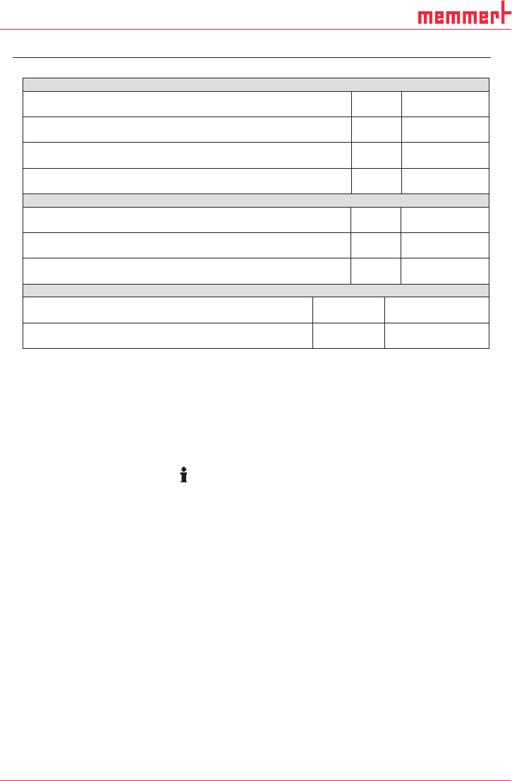
Ausgangssignal Fehler U
Flt
/ Output signal fault U
Flt
Eingangspegel „high“ Fehler vorhanden
Input level „high“ error detected
[V]
5
[3.9 … 5.5]
Eingangspegel „low“ kein Fehler
Input level „low“ no error
[V]
0
[0 … 0.9]
Max. Strombelastbarkeit
Max. current carrying capacity
[mA] 10
Ausgangsimpedanz @ 1kHz
Output impedance @ 1kHz
[kΩ] ≥ 9
Eingangssignal Remote EIN/AUS U
Rmt
/ Input signal Remote ON/OFF U
Rmt
Eingangspegel „high“ Motor EIN
Input level „high“ motor ON
[V]
5
[3.9 … 5.5]
Eingangspegel „low” Motor AUS
Input level „low” motor OFF
[V]
0
[0 … 0.9]
Eingangsimpedanz @ 1 kHz
Input impedance @ 1 kHz
[kΩ] ≥ 1.8
Versorgung Gasballastventil U
+GB
/ Supply gas ballast valve U
+GB
Steuerspannung DC
Control voltage DC
[V] 24 ± 10%
Max. Stromaufnahme
Max. current consumption
[mA] ≤ 50
Tab. 9 (part 3): Connection plan motor electronics
The flow rate can be varied by an external actuation (Sub-D-plug,
see Tab. 9).
The speed of the pump is controlled by a control voltage.
Please contact our KNF customer service for further information.
Remote ON/OFF is through an 9-pin controller connection (Pin 8,
see Tab. 9).
To start the motor, Pin 5 must be bridged to the ground of the
controller connection.
Please contact our KNF customer service for further information.
Switching off the pump
The life of the diaphragm is prolonged the formation of condensate
is avoided. Therefore the following precautions should be taken:
Run the pump for a few minutes to warm it up before handling
saturated or nearly saturated vapors.
KNF recommends: When transferring aggressive media, flush
the pump prior to switch off (see Chapter 8.2.1) to increase the
service life of the diaphragm.
Switch off pump with power switch (Fig. 1 at Chapter 5).
Restore the system to normal atmospheric pressure (release
pneumatic pressure in pump).
Pull out the pump’s main plug.
Adjusting the flow rate
Remote ON/OFF
Vapors as media
31
D39489 | Date 12/2019
Servicing Diaphragm pump PJ25481-950.50.18
20 Translation of original Installation Instructions, english, KNF 125530-316634 06/18
8. Servicing
8.1. Servicing schedule
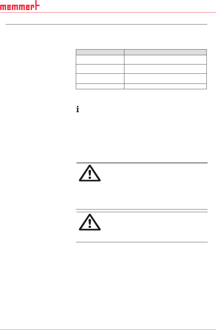
Component
Servicing interval
Pump
-
Regular inspection for external
damage or leaks
Hose connections
-
Regular inspection for external
damage or leaks
Diaphragm and valve
plates
-
Replace when pumping capacity
decreases, or sooner
Silencer
-
Change if it is dirty
Tab. 10
8.2. Cleaning
When cleaning, make sure that no liquids enter the inside of
the housing.
8.2.1. Flushing pump
Before switching off the pump, flush it with air (or with inert gas
if required for safety reasons) under atmospheric conditions
(ambient pressure) for about five minutes.
8.2.2. Cleaning pump
Pump disconnected from mains and de-energized.
WARNING
Dangerous substances in the pump can cause a
health hazard.
Depending on the substance transferred, caustic
burns or poisoning are possible.
Wear protective clothing if necessary, e.g. pro-
tective gloves.
Take the proper steps to clean the pump.
CAUTION
Danger of burns from hot pump parts
The pump head or motor may be hot even after the
pump has been shut off.
Allow the pump to cool off after operation.
Solvent should be used for cleaning only if the head materials
are not corroded (ensure compatibility of the material).
If compressed air is available, blow out the parts.
Requirements
32
D39489 | Date 12/2019
Diaphragm pump PJ25481-950.50.18 Servicing
Translation of original Installation Instructions, english, KNF 125530-316634 06/18 21
8.3. Replacing diaphragm and reed valves
Pump disconnected from mains and de-energized
Pump is clean and free of hazardous materials.
Hoses removed from pump’s pneumatic inlet and outlet.
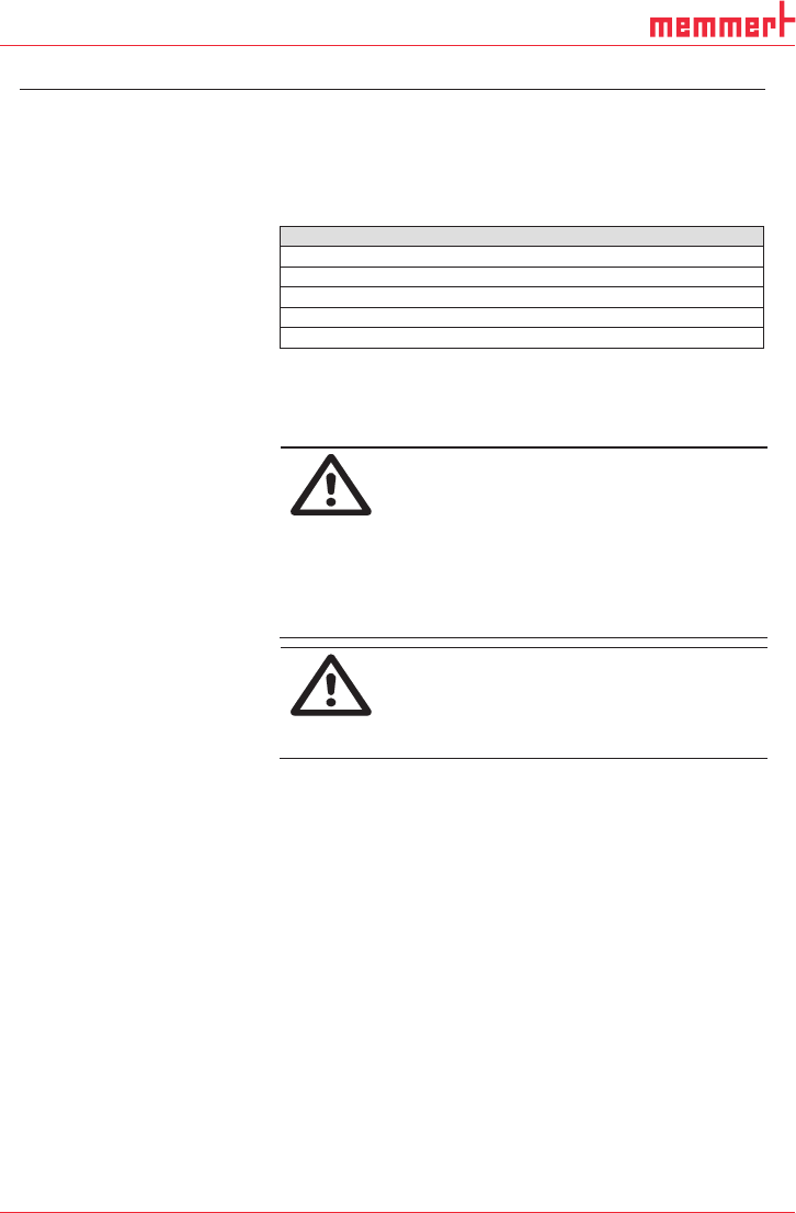
Spare part/tool
Spare parts set according to spare parts list, Chapter 10
Allen key 2-mm (hexagon)
Phillips screwdriver No. 2
Allen key 4-mm (hexagon)
Felt-tip pen
Tab. 11
Always replace diaphragm and valve plates together to main-
tain the pump performance.
WARNING
Dangerous substances in the pump can cause a
health hazard.
Depending on the substance transferred, caustic
burns or poisoning are possible.
Wear protective clothing if necessary, e.g. pro-
tective gloves.
Flush the pump before replacing the diaphragm
and valve plates (see Chapter 8.2.1).
CAUTION
Danger of burns from hot pump parts
The pump head or motor may be
hot even after the
pump has been shut off.
Allow the pump to cool off after operation.
Requirements
Spare parts/tools
Information on procedure