Workcell-Installation-Guidelines-Troubleshooting-Maintenance-REV-G.pdf - 第15页
Workcell Installation and General Guidelines Revision G / Nov ember 2021 Page 15 of 60 Figure 3: Adjust t h e Feet 6. Gently lower the workcell an d remove the forklif t. It is not necessary t o tighten the lock nuts at …

Workcell Installation and General Guidelines
Revision G / November 2021
Page 14 of 60
Installation and Setup
Before you operate the workcell, know the components. Do the steps in this manual for
safe and correct operation.
WARNING: Only qualified personnel should do these procedures. Obey this manual and
all applicable safety regulations. A “qualified person” is defined as “a person or
persons who, by possession of a recognized degree, certificate, or professional
training, or who, by extensive knowledge, training, and experience, has successfully
demonstrated the ability to solve problems relating to the subject matter and work.”
(Ref. ANSI/ASME B30.2-1983.)
Uncrate and Inspect
1. Use the utility knife to cut the straps and the shrink wrap.
2. Remove the cardboard as well as all packing materials and straps.
3. Use a 9/16” wrench to remove the bolts that anchor the workcell to the floor of the
crate, there are two (2) bolts in each foot (8 Total).
4. Use a forklift to gently remove the workcell off the pallet. Lift the workcell from
either the back or the front. Make sure the forks are all the way in and that the
blades go all the way under the workcell (from front to back).
To Place the Dispense System
1. Move the workcell to the necessary location.
2. Adjust the forklift height until the workcell is at the necessary height.
3. Loosen the lock nuts on each foot of the workcell, if necessary.
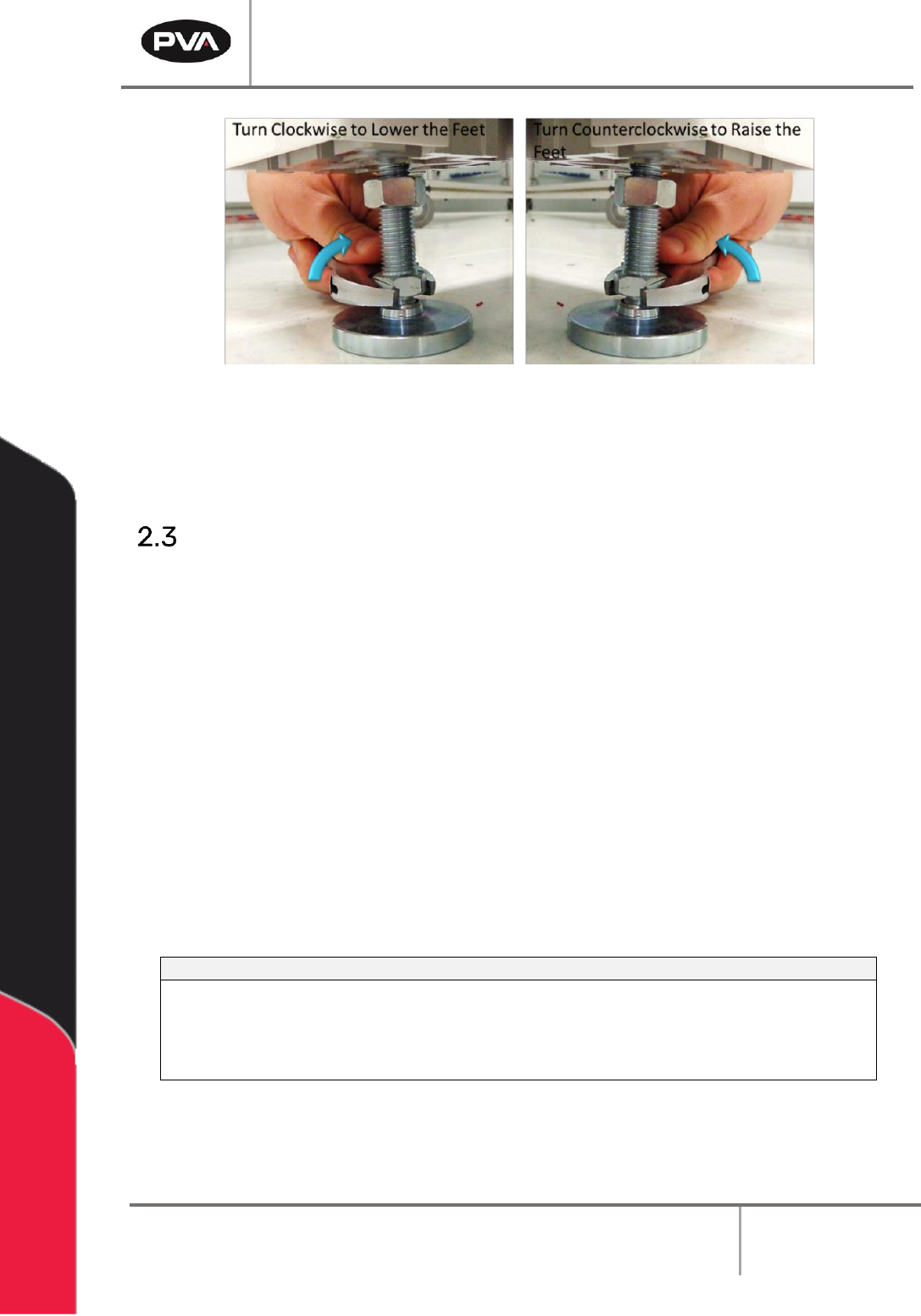
4. Make sure that all four (feet) touch the ground. If any feet do not touch the ground,
use the adjustable wrench to lower the feet by turning the feet clockwise.
5. When you lower the feet, you raise the workcell. When you raise the feet, you lower
the workcell.
See Figure 3 on next page.
Workcell Installation and General Guidelines
Revision G / November 2021
Page 15 of 60
Figure 3: Adjust the Feet
6. Gently lower the workcell and remove the forklift. It is not necessary to tighten the
lock nuts at this time.
Light Tower Operation
Three stacked indicator lights and a buzzer are used to show the machine status. The
lights are green, amber, and red and can be seen from all sides of the machine. The buzzer
is below the green light. The lights and buzzer operate as follows:
• The green light is on when the machine is in cycle and parts are made. It is off at all
other times.
• The amber light is on when the machine is in Auto Cycle and ready to make parts, but
cannot cycle because the workcell is waiting for another machine or there is an
external material handling problem (no incoming parts or no room to unload parts).
• The red light is on steady when the machine is not in Auto Cycle. It will flash when the
workcell is in an error state.
• The buzzer operates with the red light during machine errors.
212B244BState
213B245BRed
214B246BAmber
215B247BGreen
216B248BBuzzer
217B249BCycle Stop
218B250BON
219B251BOFF
220B252BOFF
221B253BOFF
222B254BAuto Cycle
223B255BOFF
224B256BON
225B257BOFF
226B258BOFF
227B259BIn Cycle
228B260BOFF
229B261BOFF
230B262BON
231B263BOFF
232B264BMachine Error
233B265BFLASH
234B266BOFF
235B267BOFF
236B268BFLASH
Figure 4: Light Tower & Buzzer Status
Note: This is the standard configuration. Actual configuration depends on the
workcell.
Workcell Installation and General Guidelines
Revision G / November 2021
Page 16 of 60
Board Sensor Sensitivity Adjustment Procedures
Board sensors are optic sensors that face upward along the length of the front of the
conveyors. They detect the presence of a part and send a signal to the motion controller. If
a board is reflective or shiny, or does not process correctly adjust the board sensors.
The number of sensors depends on your system, but your workcell may have up to five
board sensors. There can be one for each zone (entry zone, primary spray/work area, exit
zone, return work area, and part detection). Adjust each sensor as necessary.
To Adjust the Board Sensors
You will need a small flat head screwdriver and part or sample board to be processed.
1. Put a part on the conveyor’s rail and examine sensor sensitivity.
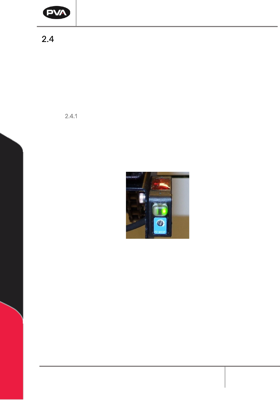
2. To increase sensitivity, use a small screwdriver to turn the sensor screw clockwise.
To decrease sensitivity turn the sensor screw counterclockwise.
Figure 5: Board Sensor
3. Use the sample part to examine the board sensors on both sides (top and bottom) of
the conveyors.
4. If only the green LED is on, the sensor is OFF. If the Orange LED is on the sensor is ON.