Workcell-Installation-Guidelines-Troubleshooting-Maintenance-REV-G.pdf - 第58页
Workcell Installation and General Guidelines Revision G / Nov ember 2021 Page 58 of 60 8. You can also acess the PVA Support Hub from “PVA Sup port Hub” option in the header or through the li nk https://support. pva.net/…
Workcell Installation and General Guidelines
Revision G / November 2021
Page 57 of 60
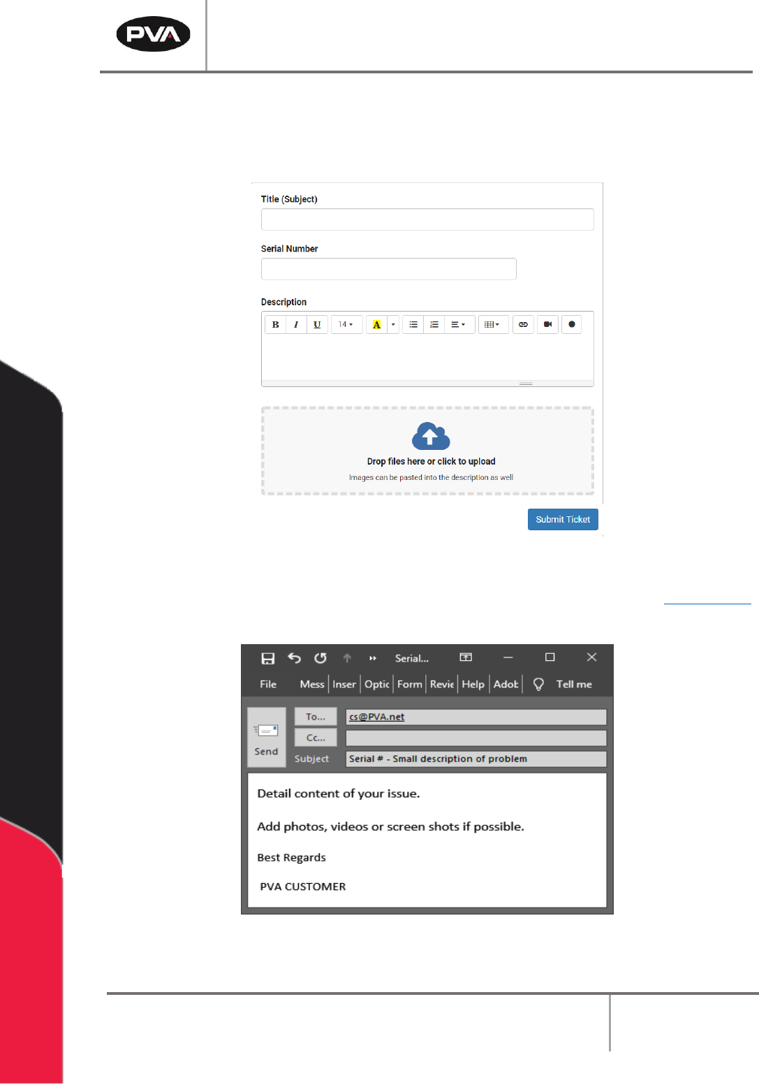
5. Fill in the information requested and use as much detail as possible. Include the
equipment serial number and any screenshots, photos, or videos.
6. Once complete, select “Submit Ticket.”
Figure 42: Complete the Ticket
7. If you cannot access the PVA Support Portal, email customer service at cs@PVA.net
to create a ticket. To reply to a ticket email, select Reply (not Reply All).
Figure 43: Example Ticket Email
Workcell Installation and General Guidelines
Revision G / November 2021
Page 58 of 60
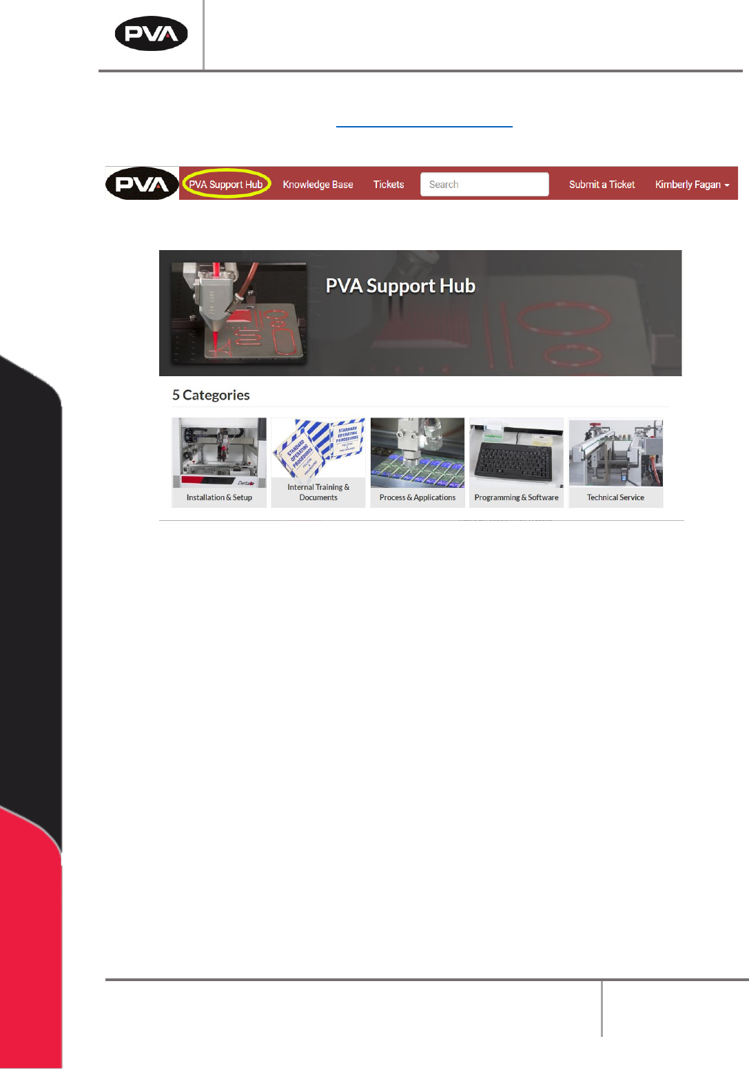
8. You can also acess the PVA Support Hub from “PVA Support Hub” option in the
header or through the link https://support.pva.net/. The support hub has processes
and procedures on common topics and issues.
Figure 44: PVA Support Hub
Figure 45: Support Hub Website

Workcell Installation and General Guidelines
Revision G / November 2021
Page 59 of 60
Table of Figures
Figure 1: Workcell Functional Block Diagram .................................................................................... 10
Figure 2: Light Tower & Buzzer Status .............................................................................................. 13
Figure 3: Adjust the Feet ....................................................................................................................... 15
Figure 4: Light Tower & Buzzer Status .............................................................................................. 15
Figure 5: Board Sensor .......................................................................................................................... 16
Figure 6: Servo Couplings ..................................................................................................................... 17
Figure 7: Shipping Bracket .................................................................................................................... 18
Figure 8: Teach Pendant Connection ................................................................................................. 19
Figure 9: Light Tower Connection ...................................................................................................... 20
Figure 10: Example of a Red Air Lockout Valve ............................................................................... 22
Figure 11: Example of a Main Power Switch ..................................................................................... 23
Figure 12: SMEMA Diagram .................................................................................................................. 24
Figure 13: SMEMA Machine Plugs ....................................................................................................... 24
Figure 14: Measure Velocity at Port .................................................................................................... 27
Figure 15: Measure Velocity at Duct Inlet .......................................................................................... 27
Figure 16: Portal Shell ........................................................................................................................... 28
Figure 17: Workcell Manual Location .................................................................................................. 28
Figure 18: Systems Fault Diagnosis .................................................................................................... 31
Figure 19: Preventive Maintenance Schedule ................................................................................. 33
Figure 20: Terminal Window ................................................................................................................. 37
Figure 21: Terminal Screen Commands ............................................................................................ 38
Figure 22: Encoder Feedback Test .................................................................................................... 40
Figure 23 ................................................................................................................................................... 41
Figure 24: Setup New Controller ......................................................................................................... 41
Figure 25: Controller Models ............................................................................................................... 42
Figure 26: Connection Type ................................................................................................................ 42
Figure 27: Serial Parameters ............................................................................................................... 43
Figure 28: Controller Added ................................................................................................................ 43
Figure 29: Edit Registry ........................................................................................................................ 44
Figure 30: Change Controller .............................................................................................................. 44
Figure 31: Variable Explanations......................................................................................................... 45
Figure 32: Irradiator Bulb Side ............................................................................................................ 45
Figure 33: Install Irradiators ................................................................................................................ 46
Figure 34: Connect Lamp Cables ....................................................................................................... 46
Figure 35: Turn Lamp Power Supply On ........................................................................................... 47
Figure 36: Important Commands ....................................................................................................... 53
Figure 37: DMC Error Codes ................................................................................................................. 54
Figure 38: Support Portal ..................................................................................................................... 55
Figure 39: Log In .................................................................................................................................... 55
Figure 40: Sign In or Register .............................................................................................................. 56