Workcell-Installation-Guidelines-Troubleshooting-Maintenance-REV-G.pdf - 第37页
Workcell Installation and General Guidelines Revision G / Nov ember 2021 Page 37 of 60 Motor Feedback Tes t Use this procedur e to make sure that the motor power and Hall Effect sensors are wired correctly. If a problem …

Workcell Installation and General Guidelines
Revision G / November 2021
Page 36 of 60
Pressure Differential Switch Setup
Note: The flow velocities referred to are only valid for a 5” duct diameter.
1. Turn on the exhaust at 100% speed.
2. Examine the operation of the pressure switch input. The input should be “ON” with
the exhaust at 100% speed.
3. Turn off the exhaust. Make sure the pressure switch input turns “OFF”.
4. Decrease the outlet of the exhaust until the airflow velocity is between 2200-2350
ft/min (300-320 CFM) at the exhaust flange screen.
5. Make sure that the exhaust pressure switch input is still “ON”. If it is not, turn the
adjustment screw counterclockwise until the input turns “ON”.
6. Turn off the exhaust. Make sure the pressure switch turns “OFF”.
7. Turn on the exhaust. Make sure the pressure switch input turns “ON”. If not, turn the
adjustment screw counterclockwise again until the input turns “ON”. Make sure that
the input turns “OFF” when the exhaust is turned off.
8. Decrease the outlet of the exhaust until the airflow velocity is between 1840-2000
ft/min (250-275 CFM) at the exhaust flange screen.
9. Make sure that the pressure switch input stays “OFF” at this airflow velocity. If the
input stays “ON”, turn the adjustment screw clockwise SLOWLY until the input turns
“OFF”.
10. If an adjustment is made, make sure the input at the airflow velocity used in step 4
still operates. The input should still turn “ON” at an airflow velocity within the range
used in step 4.
11. Set the exhaust to off and back on again. Make sure that the pressure switch input
stays “OFF” for an airflow velocity within the range used in step 8.
Workcell Installation and General Guidelines
Revision G / November 2021
Page 37 of 60
Motor Feedback Test
Use this procedure to make sure that the motor power and Hall Effect sensors are wired
correctly. If a problem is found with any of the axes, repair it and tell a production supervisor.
WARNING! Make sure that the workspace has no parts or objects in it. If the axis runs
away, the machine can be irreversibly damaged.
1. Turn the machine “ON”.
2. Engage the “Emergency Stop” button. This stops the power to the amplifiers.
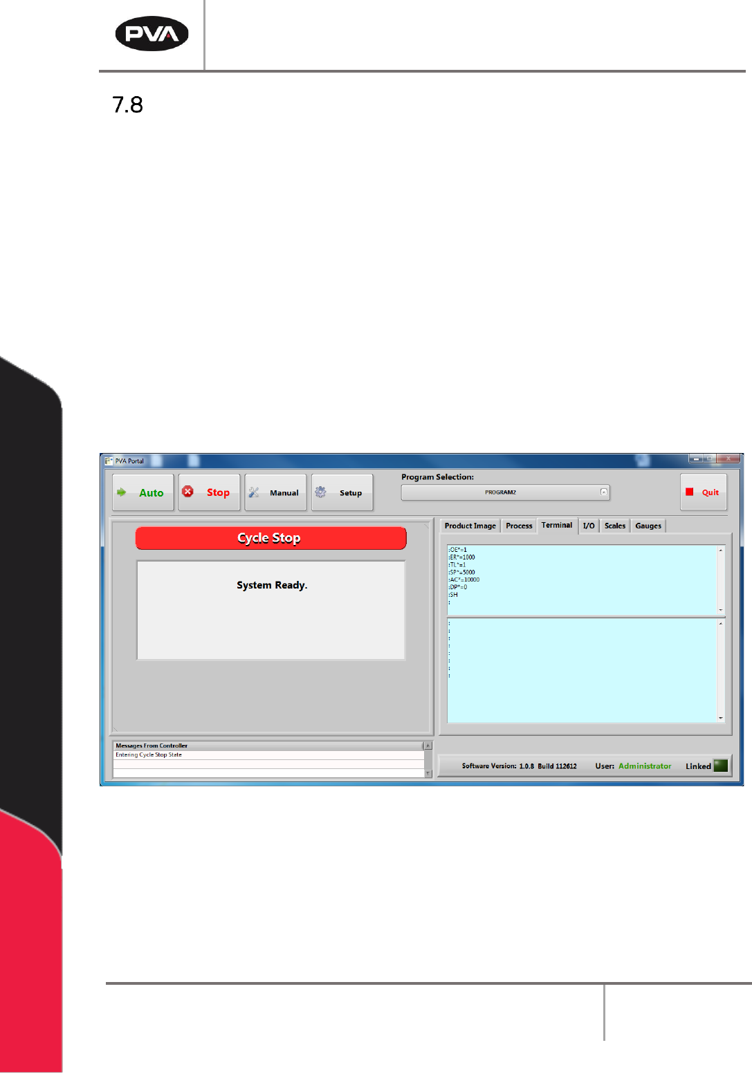
3. Open a terminal program and establish communication with the motion controller,
this can be done with the ‘terminal’ option in PathMaster® or PVA Portal.
4. Enter HX and MO in the terminal screen
5. Disengage the “Emergency Stop” push button.
Figure 20: Terminal Window

Workcell Installation and General Guidelines
Revision G / November 2021
Page 38 of 60
The motors may be wired incorrectly. The program below limits the acceptable error and
power available to the amplifiers. This protects personnel and equipment.
6. Enter the commands that follow on the terminal screen.
OE*=1
Off-on-error enabled for all axes
ER*=1000
Error limit for all axes
TL*=1
Torque limit of 1 for all axes
SP*=5000
Set the speed
AC*=10000
Set the acceleration
DP*=0
Define the current position as (0, 0, 0, 0)
SBN
Enable power (only on machines without a POWER ON button) where N = the
control output power bit, refer to electrical schematic or call PVA Technical
Support
SH
Apply power to the servo motors
Figure 21: Terminal Screen Commands
7. Push the “POWER ON” button (if present) so it lights up. This restores power to the
amplifiers. Use caution, any of the axes can move at this time.
8. Enter an X-axis positive move command. If the axis runs away, debug and do the
procedure again.
PRX=2000
BGX
If the results are not correct, make sure the command was entered correctly and repeat the
previous tests.
9. Enter the command to see the current position and position error, TP; TE.
10. Enter an X-axis negative move command. If the axis runs away debug and do the
procedure again.
PRX=-2000
BGX
11. Enter the command to see the current position and position error, TP; TE.
12. Repeat step 6 through 10 for the Y, Z and W axes. Replace the X in both commands
with the necessary axis. Example for the Y axis it would be:
PRY=2000
BGY