Workcell-Installation-Guidelines-Troubleshooting-Maintenance-REV-G.pdf - 第29页
Workcell Installation and General Guidelines Revision G / Nov ember 2021 Page 29 of 60 Troublesho oting The troublesho oting section is designed to solve proble ms before y ou call PV A for help. Use this section if a me…
Workcell Installation and General Guidelines
Revision G / November 2021
Page 28 of 60
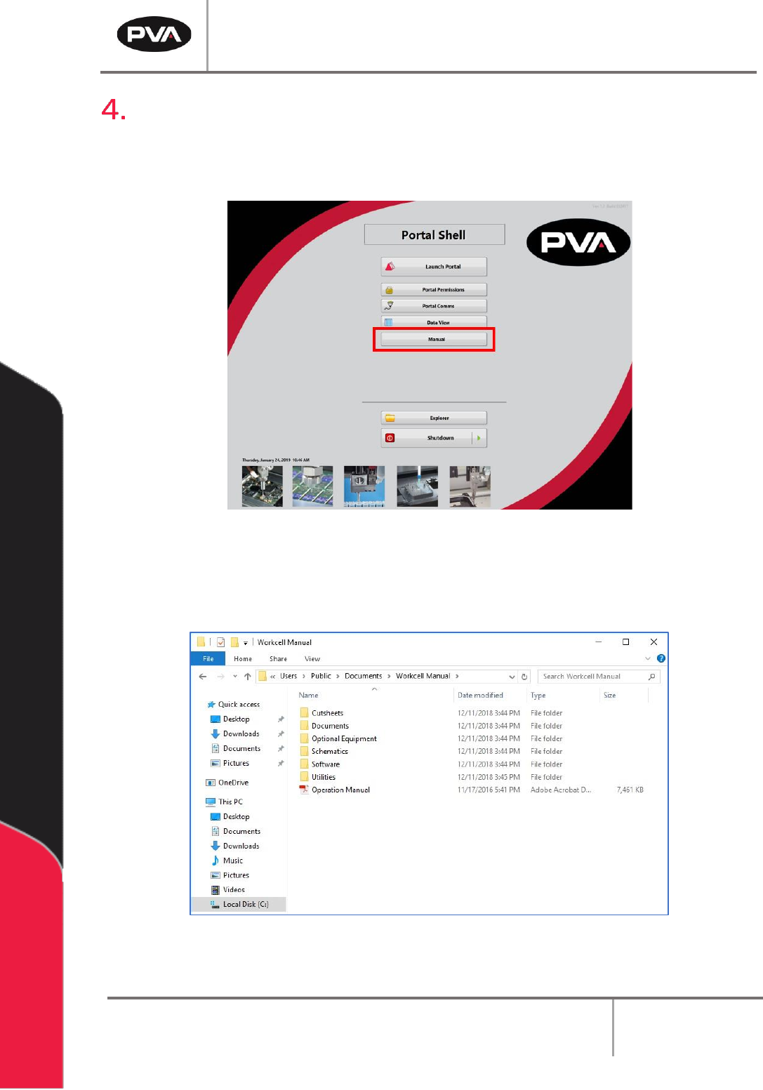
Manual Location
Your manual is saved to your workcell’s PC (if you have one).
1. To find your manual, start the workcell computer and open Portal Shell.
Figure 16: Portal Shell
2. Select the “Manual” button.
3. The file location will display all of the documentation for your workcell.
Figure 17: Workcell Manual Location

Workcell Installation and General Guidelines
Revision G / November 2021
Page 29 of 60
Troubleshooting
The troubleshooting section is designed to solve problems before you call PVA for help. Use
this section if a mechanical or electrical problem occurs. If you have problems that are not
listed in this section, or continue to have problems after you have done different
procedures, please contact PVA Technical Support.
Note: If a problem occurs while running a particular path program, consult the
separate PathMaster® Manual for information on debugging code problems.
Calling Technical Support
The technical support staff is available to help solve any problems. The phone number is
+1-518-371-2684. Before you call for help, make sure you have information or
documentation for the following items:
1. Please have the serial number of the machine(s) available.
2. Record all the information from the Portal screen when the error occurred.
3. Record the operation that was in progress when the machine had the problem
(when did it have problems, what was it doing, etc.).
4. If the error was not dangerous or damaging, try to cause the error again. If the error
does not occur again, the problem may have been operator generated.
5. Use a terminal screen to communicate with the motion controller. It is necessary to
give commands directly to the motion controller for most troubleshooting.
6. If the problem is programming related, a hard copy or email of the program in
question may be requested by PVA, please be prepared to send one. The PVA fax
number is (518) 371-2688, or the technical support representative will provide an
email address.
Records
Any service or replaced components should be recorded in maintenance records with any
other pertinent data for future reference.

Workcell Installation and General Guidelines
Revision G / November 2021
Page 30 of 60
Fault Diagnostic for Closed Loop Servo Systems
The workcell uses a closed loop servo drive system. Shown below is a general fault diagnostic
table for this type of system.
Problem
Other Symptoms
Possible Cause
Corrective Action
When the axes
are homed, the
end effector
moves past the
home sensor
and hits the
hard stop
Home sensor is out of
position or too far away
from the homing tab
• Engage the “Emergency Stop”
button. Use your hand to move the
axis so the homing tab moves into
the home sensor, and the sensor is
on. Loosen the lock nut on the
sensor and adjust to .020” gap
Sensor cable is loose or not
connected
• Check the cable connections and
correct any loose connections
When the axes
are homed, the
Z-axis does not
move
SSR-1 is not ON
when the Z-axis
drive is enabled
The Z-axis brake does not
disengage when the drive
is enabled
• Examine the SSR-1 wiring, it
should be on when the Z- axis
drive is enabled
SSR-1 is ON when
the Z-axis drive is
enabled
The fuse for SSR-1 is blown
or damaged
• Examine the fuse with an OHM
meter and replace if necessary
Note: *If the SSR is on that does not mean it is functioning correctly. Use the test procedure for SSR5 in
the power check relay document to test SSR1 for correct operation.
The axis does
not have any
motion
Encoder works
according to the test
in Section 13.6
Axis speed/ acceleration is
set to zero
• Set the speed and acceleration to
a positive, non-zero value with the
SP and AC commands
The axis drive light is
RED
The axis drive is not
enabled
• Enable the drive with the SH
command
The axis cables are loose or
not connected
• Examine the cable connections
and repair any loose connections
The “Emergency Stop”
button is engaged
• Disengage the “Emergency Stop”
button
Hall Effect sensors are not
correctly connected
• Examine the cable connections for
the axis, and correct any loose
connections
• Use the electrical drawings to
make sure the Hall Effect sensor
phasing is correct
The axis amplifier is bad
• Replace the amplifier
Doors are open
• Close the doors tightly
The axis runs
away
Axis encoder does
not work
Motor power connections
are wired incorrectly
• Use the electrical drawings to
make sure the phasing is correct
Axis encoder/brake cable
is loose or not connected
• Examine the cable connections,
and repair any loose connections
The axis amplifier is bad
• Replace the amplifier