Workcell-Installation-Guidelines-Troubleshooting-Maintenance-REV-G.pdf - 第23页
Workcell Installation and General Guidelines Revision G / Nov ember 2021 Page 23 of 60 7. Ground any pressure v essel to earth or th e machine. 8. Attach a correctly desig ned ventil ation system to the exhaus t port. It…
Workcell Installation and General Guidelines
Revision G / November 2021
Page 22 of 60
Power Up
After the accessories are installed, connect the workcell to air and power supplies. After
the workcell is correctly connected, turn the main power switch “On” and make sure
system components function correctly.
WARNING: Failure to obey electrical specifications can damage the machine and
injure personnel. Electrical hookup must be done by a qualified electrician and must
comply with any applicable local standards.
1. Plug the machine into an appropriate power source as shown on the legend plate on
the rear of the machine.
The electrical service must be correctly grounded and the power source “clean”. If high-
power equipment uses the same source, a line conditioner may be necessary. Poor power
quality can cause machine errors. All workcells shipped from the PVA factory can operate
with the voltage used at the installation site, per engineering design.
WARNING: Make sure that the main power switch is “Off” before you connect the
workcell to the facility power source.
2. Find the main air regulator.
3. Attach the workcell to the facility air supply. There is a ¼” NPT female fitting at the
rear of the machine. Connect to a source of clean, dry air. Compressed air with a
dew point of 50° F (10° C) is sufficient. A hose with ¼” inside diameter is sufficient
for most machines and typical air consumption is 2-6 CFM (3.4 to 10.2 m^3/hr).
4. Slowly open the facility air valve.
5. Close any access doors and engage in the Emergency Stop button.
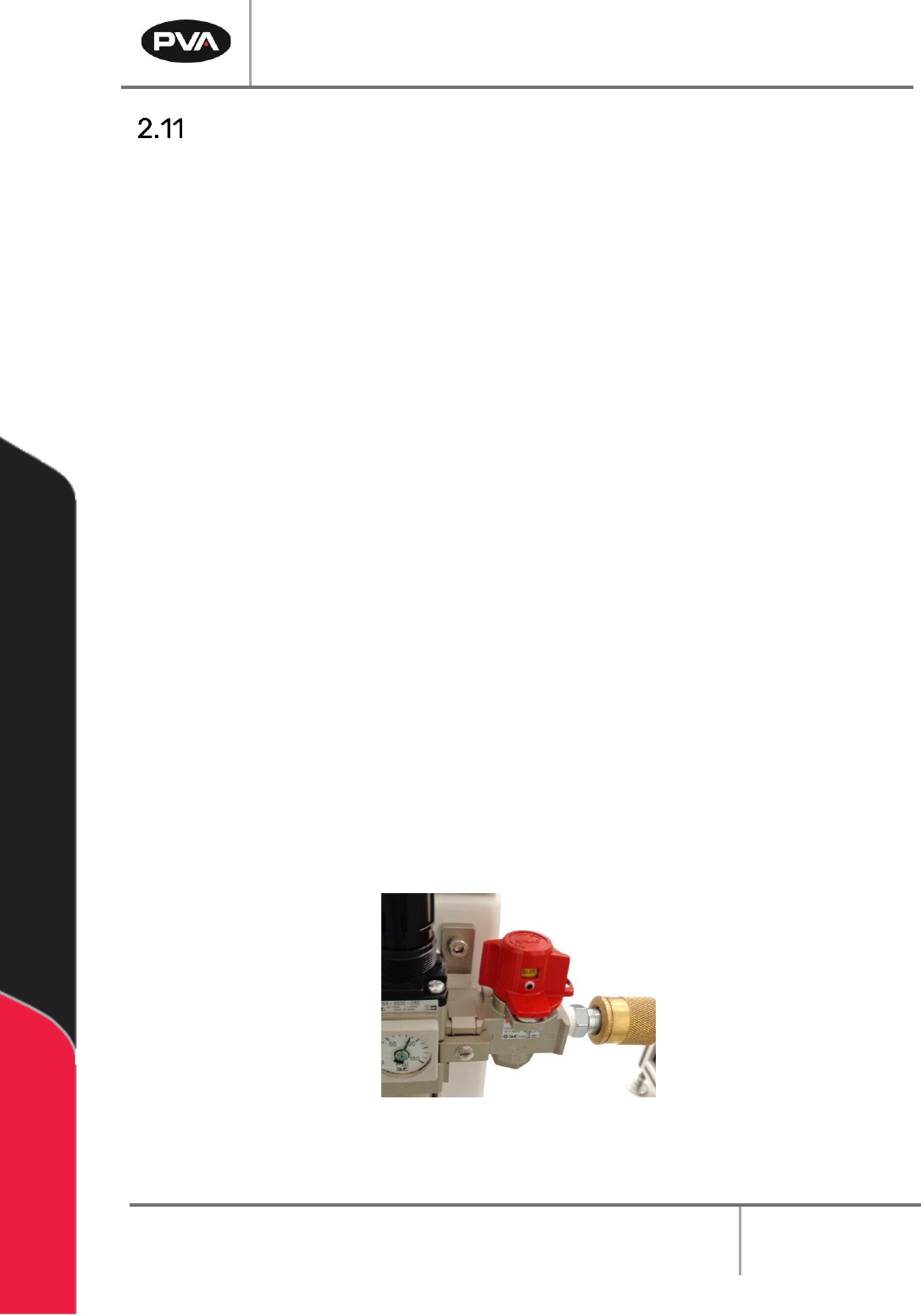
6. At the rear of the machine, turn on the red air lockout valve.
Figure 10: Example of a Red Air Lockout Valve
Workcell Installation and General Guidelines
Revision G / November 2021
Page 23 of 60
7. Ground any pressure vessel to earth or the machine.
8. Attach a correctly designed ventilation system to the exhaust port. It is necessary
that the exhaust flow is correct for the specified CFM of your workcell.
NOTE: Refer the Material Safety Data Sheets (MSDS) for safety precautions on any
chemicals used in PVA equipment.
NOTE: Do not power on the workcell or add material to the pressure vessels until they
are correctly grounded.
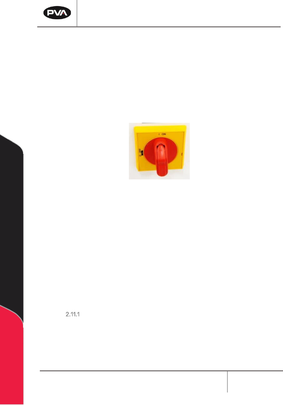
9. Turn the main power switch “On”.
Figure 11: Example of a Main Power Switch
10. Do the safety check and homing routine through Portal.
11. Select Manual mode and manually (using teach pendant) move the head around the
entire work area. Make sure there are no components that can be hit by the head in
the work area.
12. Make sure that the pneumatic and electrical cables do not decrease the heads travel
and will not be cut or snagged when moved. Please contact Technical support if
there are any problems.
13. Make sure the valve and brackets are tight and that the valve does not rock or
wiggle in the bracket.
14. Close the doors.
LCD Mounting Requirements
If a monitor will be mounted on a PVA arm it must:
• Weigh no more than 9 lbs.
• Have either 75mm or 100mm hole spacing for the VESA mount.
• Be flat on rear of the monitor for PVA keyboard tray bracket.
Workcell Installation and General Guidelines
Revision G / November 2021
Page 24 of 60
Machine Communications (SMEMA)
For manufacturing lines (multiple machines with conveyor systems) SMEMA cables must
be connected in the correct manner for the individual modules to communicate reliably.
Not all workcells have SMEMA plugs. Please note on the diagrams the J# refers to the label
on the machine, not the label on the cable.
The Surface Mount Equipment Manufacturers Association (SMEMA) Electrical Equipment
Interface Standard is used to make sure the sequence of boards is correct. If you do not
have these connections, boards cannot move from one machine to another. SMEMA cables
have male 14-pin, amp-type CPC connectors. The cables are straight through, so
orientation does not matter. SMEMA machine plugs may be on the inside or the outside of
the machine, depending on the workcell.
Each machine must have the same transport conveyor height from the floor to the bottom
of the PC board. For equipment with an adjustable conveyor width, the front rail is not
adjustable. The range of adjustment will change with the workcell.
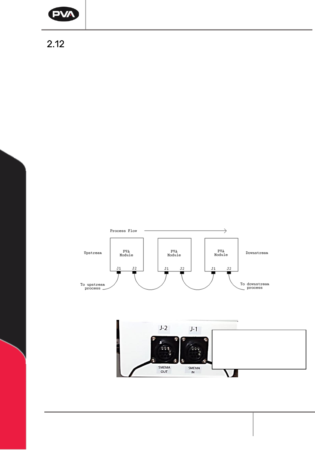
Two signal lines will be used: Ready and Board Available. On each module, the cable to the
J1 (Previous) plug must connect to the J2 (Next) plug on the machine upstream. The J2
plug on each machine must connect to the J1 plug on the machine downstream, as shown
in the following diagram:
Figure 12: SMEMA Diagram
Figure 13: SMEMA Machine Plugs
NOTE: For bidirectional
machines there may be J3
and J4 that follow J1 and
J2 respectively.