Workcell-Installation-Guidelines-Troubleshooting-Maintenance-REV-G.pdf - 第40页
Workcell Installation and General Guidelines Revision G / Nov ember 2021 Page 40 of 60 17. Tu rn the workcell “ OFF ”. 18. Connect the motor po wer cables. 19. Turn the work cell “ ON ”. Figure 22 : Encoder Feedb ac k Te…

Workcell Installation and General Guidelines
Revision G / November 2021
Page 39 of 60
Encoder Feedback Test
Use this procedure to test the encoder feedback for all of the axes. If a problem is found with
any of the encoders, repair it and then report the error to a production supervisor. Most
encoders used with Portal generate 5080 counts/inch. Make sure that the position feedback
is in the correct range.
(500*4 counts/rev)*(1 rev/cm)*(2.54 cm/in) = 5080 counts/inch.
1. Turn the machine “OFF” and disconnect the motor power.
2. Move all of the axes to the center of travel position.
3. Turn the machine “ON”.
4. Login to PVA Portal.
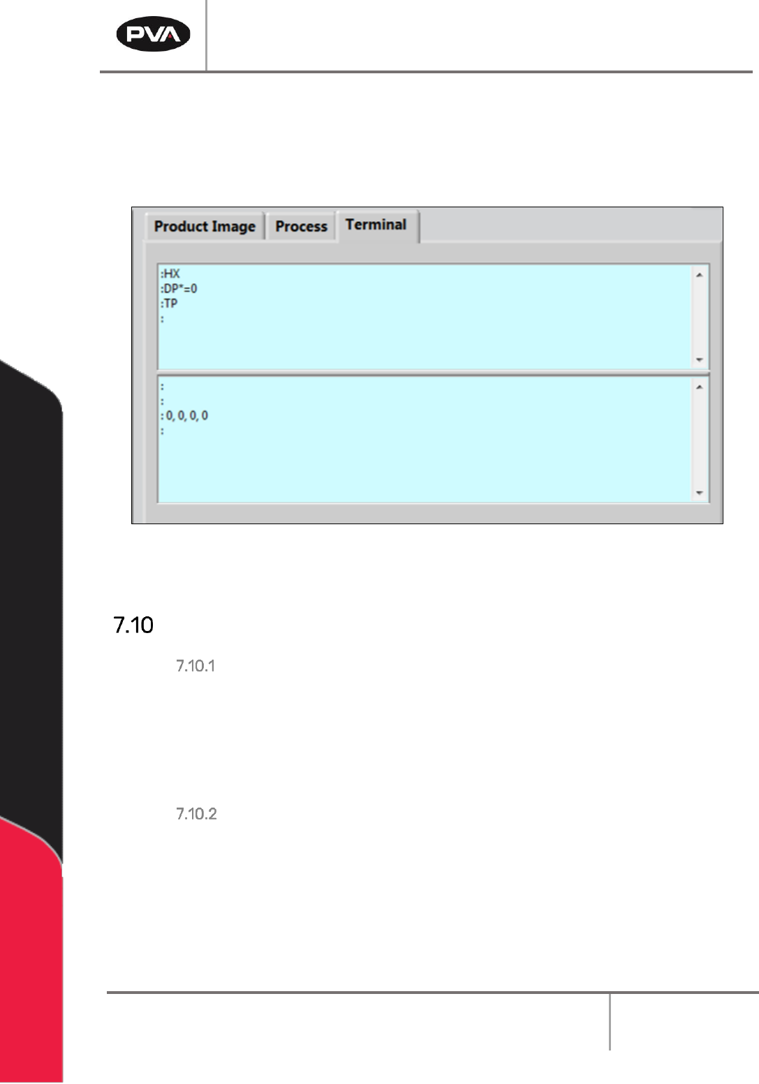
5. Select the terminal tab. Push “Enter”. You should see a colon response.
6. Enter HX.
7. Define the current position as (0, 0, 0, 0). Enter DP*=0.
8. Use your hand to move the X-axis in the positive direction and look at the current
position. The current position should reflect the numbers listed above (5080
counts/inch, 2000 counts/rev, or 200 counts/mm).
9. Enter TP.
10. Refer to step 10 for steps 13-19.
11. Move the X-axis in the negative direction and look at the current position.
12. Move the Y-axis in the positive direction and look at the current position. Move the Y-
axis in the negative direction and look at the current position.
13. Move the Z-axis in the positive direction and look at the current position. Move the Z-
axis in the negative direction and look at the current position.
14. Move the W-axis in the positive direction and look at the current position. Move the
W-axis in the negative direction and look at the current position.
15. Select “Quit” to shutdown Portal.
16. Shutdown the PC.
Workcell Installation and General Guidelines
Revision G / November 2021
Page 40 of 60
17. Turn the workcell “OFF”.
18. Connect the motor power cables.
19. Turn the workcell “ON”.
Figure 22: Encoder Feedback Test
Computer and Workcell Communication
RS-232 Communication
A RS-232 connection will use a straight through connection. The Rx and Tx lines are
crossed internally on the controller so a null modem is not necessary. The controller baud
rate and handshaking are set with dip switches on the Galil controller inside the workcell
enclosure. Hardware handshaking must be enabled to communicate with PathMaster®
over RS-232.
DMC-2200 Dip Switch Settings
The main RS-232 port on the DMC-2200 controller must be configured as shown to
communicate with the PathMaster® software. Baud rate can be adjusted, but handshaking
must be “On”.
See Figure 23 on next page.
Workcell Installation and General Guidelines
Revision G / November 2021
Page 41 of 60
Switch
Position
Description
MRST
OFF
Master Reset Switch
XON/XOFF
OFF
Software Handshaking Switch
HSHK
ON
Hardware Handshaking Switch
9600
OFF
Baud rate
19.2K
ON
Baud rate
38.4K
OFF
Baud rate
Figure 23
Note: If hardware handshaking is enabled and a computer is not attached to the Main
RS-232 port, when the program uses the message command the controller eventually
halts. A computer must be attached to the controller when handshaking is enabled and
message commands are used.
Serial Communications
To configure serial connections do the steps below.
1. Select Setup
→
Machine Parameters from the Main menu in PathMaster to open the
Machine Parameters window.
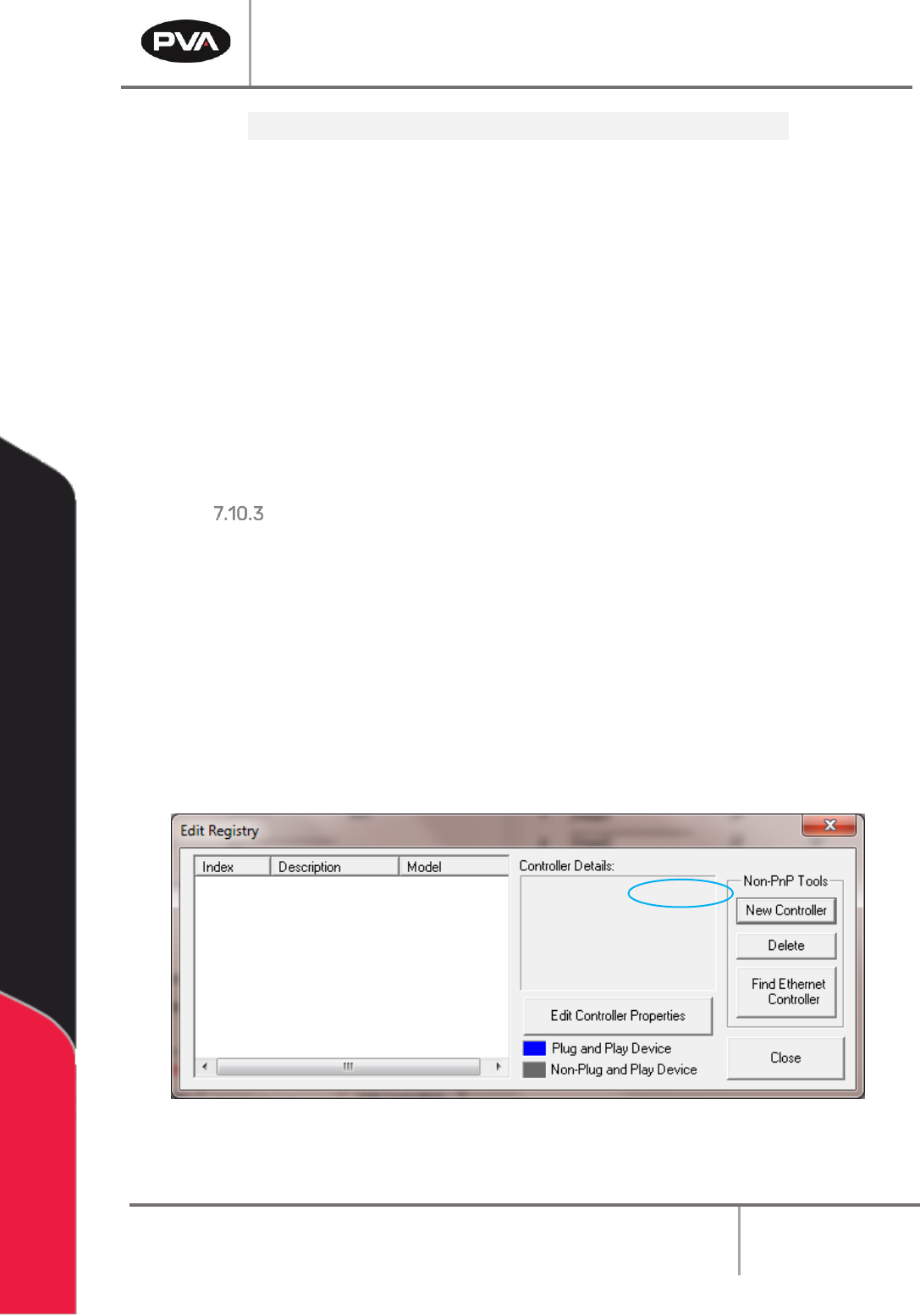
2. Select the “Edit Controllers” button in the Machine Parameters window.
3. Select “OK” if a message shows that PathMaster® could not find any controllers in
the Windows® registry. This means that no control handles have been configured yet.
4. Select “New Controller” in the Edit Registry window.
Figure 24: Setup New Controller