Workcell-Installation-Guidelines-Troubleshooting-Maintenance-REV-G.pdf - 第36页
Workcell Installation and General Guidelines Revision G / Nov ember 2021 Page 36 of 60 Pressure Differential S witch Setup No te: The flow v elocities refe rred to are only valid for a 5” duct diamete r. 1. Turn on the e…
Workcell Installation and General Guidelines
Revision G / November 2021
Page 35 of 60
Servicing the Inline Material Filter
Machines that dispense low viscosity materials may have an inline stainless-steel filter on
the pressure vessel. If material flow is reduced, the filter element could be clogged. All parts
of the filter are stainless steel and can be cleaned several times before replacing. To clean
or replace the filter:
1. Turn air supply pressure to the pressure vessel “Off”.
2. Turn the material valve on the vessel “Off”.
3. Use two large adjustable wrenches to separate the two sections of the filter.
4. Remove the stainless steel filter element, record the correct orientation.
5. Clean or replace the filter as necessary.
6. Assemble the filter and pressurize the system. It may be necessary to purge air from
the system.
7. Turn air supply pressure to the pressure vessel “On”.
8. Turn the material valve on the vessel “On”.
Exhaust Fan Setup
1. Turn the power “OFF”.
2. Open the electrical enclosure.
3. Use the dial in the overload relay in the electrical cabinet to set the overload relay
current to 1.0 * FLA for the motor. The FLA is shown on the motor nameplate.
4. Set the reset button to Manual.
5. Restart the machine.

Workcell Installation and General Guidelines
Revision G / November 2021
Page 36 of 60
Pressure Differential Switch Setup
Note: The flow velocities referred to are only valid for a 5” duct diameter.
1. Turn on the exhaust at 100% speed.
2. Examine the operation of the pressure switch input. The input should be “ON” with
the exhaust at 100% speed.
3. Turn off the exhaust. Make sure the pressure switch input turns “OFF”.
4. Decrease the outlet of the exhaust until the airflow velocity is between 2200-2350
ft/min (300-320 CFM) at the exhaust flange screen.
5. Make sure that the exhaust pressure switch input is still “ON”. If it is not, turn the
adjustment screw counterclockwise until the input turns “ON”.
6. Turn off the exhaust. Make sure the pressure switch turns “OFF”.
7. Turn on the exhaust. Make sure the pressure switch input turns “ON”. If not, turn the
adjustment screw counterclockwise again until the input turns “ON”. Make sure that
the input turns “OFF” when the exhaust is turned off.
8. Decrease the outlet of the exhaust until the airflow velocity is between 1840-2000
ft/min (250-275 CFM) at the exhaust flange screen.
9. Make sure that the pressure switch input stays “OFF” at this airflow velocity. If the
input stays “ON”, turn the adjustment screw clockwise SLOWLY until the input turns
“OFF”.
10. If an adjustment is made, make sure the input at the airflow velocity used in step 4
still operates. The input should still turn “ON” at an airflow velocity within the range
used in step 4.
11. Set the exhaust to off and back on again. Make sure that the pressure switch input
stays “OFF” for an airflow velocity within the range used in step 8.
Workcell Installation and General Guidelines
Revision G / November 2021
Page 37 of 60
Motor Feedback Test
Use this procedure to make sure that the motor power and Hall Effect sensors are wired
correctly. If a problem is found with any of the axes, repair it and tell a production supervisor.
WARNING! Make sure that the workspace has no parts or objects in it. If the axis runs
away, the machine can be irreversibly damaged.
1. Turn the machine “ON”.
2. Engage the “Emergency Stop” button. This stops the power to the amplifiers.
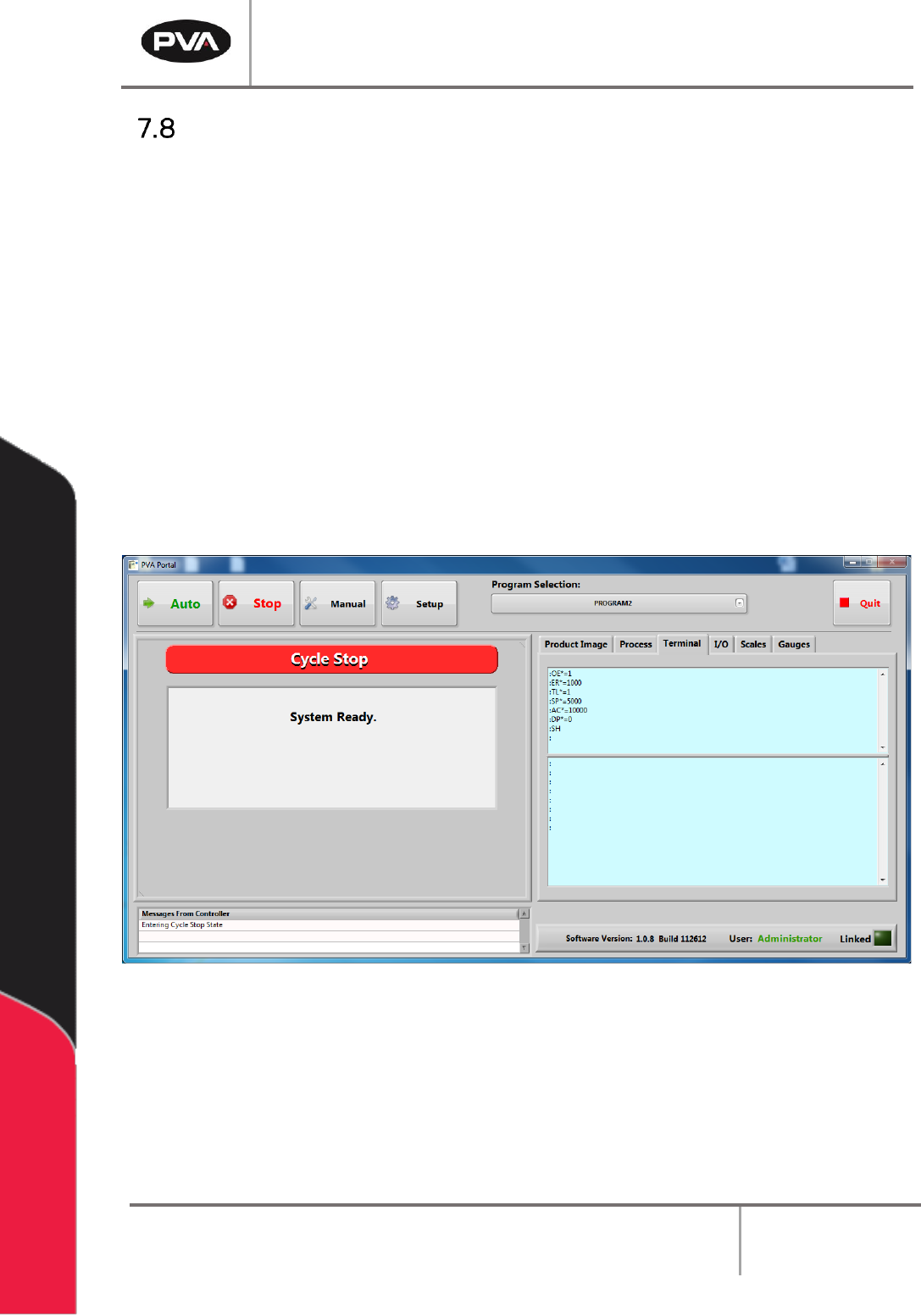
3. Open a terminal program and establish communication with the motion controller,
this can be done with the ‘terminal’ option in PathMaster® or PVA Portal.
4. Enter HX and MO in the terminal screen
5. Disengage the “Emergency Stop” push button.
Figure 20: Terminal Window