00197465-01_SM_CP20-A-M_EN.pdf - 第23页
3 Service Work Conveyor 3.3 Replacing the DP Drive [03058627-xx] Service Manual SIPLACE C&P20, C&P20A, C&P20M 23 Installation ► Use the service apertu re to insert th e new DP drive into the gu ide. ► Loosely…
3 Service Work Conveyor
3.3 Replacing the DP Drive [03058627-xx]
22 Service Manual SIPLACE C&P20, C&P20A, C&P20M
► Carefully lever the holding circuit off the locating pins. Make sure that the O-ring is not damaged.
► Pull the nozzle off the segment.
► Carefully remove the dead indexing plate from the segment.
⇨ During assembly, the old dead indexing plate is replaced with a new one.
► Disconnect the hose attached to the "vacuum supply connection" from the DP drive.
► Remove the DP drive through the service aperture.
Pay attention to the red foam ring (Sylomerring) in the star carrier. During assembly, make sure that
the edge of the end stop does not get jammed with this foam ring or be pushed onto it.
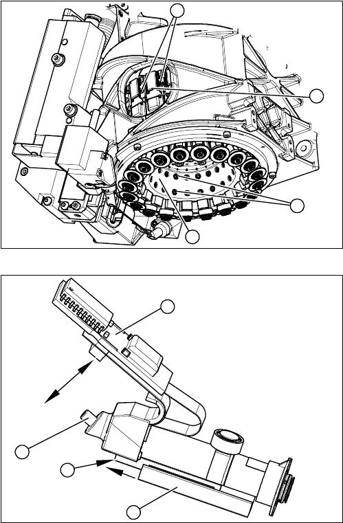
► Through the service aperture, loosen the fixtures (1)
on the left and right of the relevant DP drive board (2).
► Carefully pull the board (2) off the connector.
► Loosen the two screws (3) fastening the relevant DP
drive to the inside of the star carrier (4).
⇨ Take care not to lose the screws.
1. Board
2. Vacuum supply connection
3. Linear guide (2 x fastening screws)
4. End stop edge
4
1
3
2
1
4
3
2
3 Service Work Conveyor
3.3 Replacing the DP Drive [03058627-xx]
Service Manual SIPLACE C&P20, C&P20A, C&P20M 23
Installation
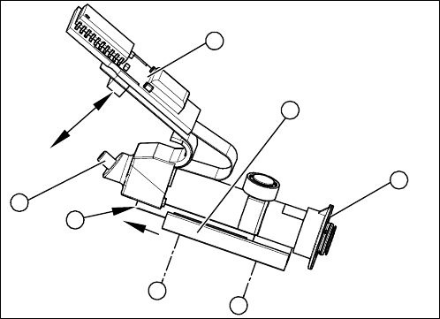
► Use the service aperture to insert the new DP drive into the guide.
► Loosely fix the linear guide with one of the fastening screws (5).
► Gently press the board onto the connectors.
► Press the linear guide against the pin.
► Carefully tighten the two fastening screws (5) and (7) with 20 Ncm.
⇨ This prevents the end stop edge from being pushed onto the red foam ring.
► Turn the star back.
► Check: the end stop edge must be just touching the red foam ring but not pushed onto it.
► Connect the hose to the compressed air supply. While doing so, check the hose for any damage and
replace it if necessary.
► We recommend that you use a suitable pair of tweezers and make sure that the hose is not bent or
damaged.
► Press the board fully onto the connector.
► Fit the mount onto the board (torque 10 Ncm).
► Attach the new dead indexing plate to the segment. Observe the groove in the dead indexing plate.
► Check that the indexing plate is seated securely on the segment especially in reference to the neigh
-
boring segments (same height).
► Fit the holding circuit and silencer.
► Follow the removal instructions in reverse order for further installation.
1. Board
2. Connection for compressed air supply
3. Linear guide rails
4. End stop edge
5. Fastening screw
6. Sleeve
7. Fastening screw
7
6
5
1
4
3
2
3 Service Work Conveyor
3.4 Replacing the Hold Circuit -Vacuum Unit [03005123-xx]
24 Service Manual SIPLACE C&P20, C&P20A, C&P20M
3.4
3.4 Replacing the Hold Circuit -Vacuum Unit [03005123-xx]
Replacing the Hold Circuit -Vacuum Unit [03005123-xx]
Parts, equipment and tools
▪ Holding circuit vacuum unit [03005123-xx]
▪ Torque screwdriver Torque Vario 10-60 Ncm [00386132-xx]
▪ Torque interchangeable blades 2.5 mm, hexagonal [03090019-xx]
▪ Tools for removing the head, if needed (see also the service manual for your machine)
Preparation
► Remove the head from the machine. For removal and installation details of the placement head, read
the service manual for your machine.
Removal
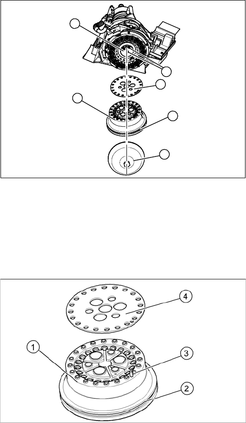
► Loosen the screw fastening the silencer and and remove the silencer.
► Loosen the three screws fastening the holding circuit.
► Carefully lever the holding circuit off the locating pins. Make sure that the O-ring is not damaged.
Installation
► Correctly position the seal disk on the holding circuit. Make sure all openings are aligned.
► If the O-ring is damaged, replace it with a new one.
► Position the holding circuit (with seal disk) correctly onto the locating pins in the star carrier.
► Fix the holding circuit into place with the three fastening screws. Tighten the screws with 35 Ncm.
1. Silencer
2. Hold circuit
3. O-ring
4. Seal disk
5. 3 x fastening screws on the holding circuit
5
1
5
4
3
2
1. Hold circuit
2. O-ring
3. Locating pins (on star carrier)
4. Seal disk