00197465-01_SM_CP20-A-M_EN.pdf - 第26页
3 Service Work Conveyor 3.6 Replacing the Seal Disk on the Hold Circuit [03005120- xx] 26 Service Manual SIPLACE C&P20, C&P20A, C&P20M 3.6 3 . 6 R e p la c in g t h e S e a l D is k o n t h e H o ld C ir c u …
3 Service Work Conveyor
3.5 Replacing the Silencer [03043707-xx]
Service Manual SIPLACE C&P20, C&P20A, C&P20M 25
► Fit the silencer. Tighten the screw fastening the silencer hand-tight.
► Follow the removal instructions in reverse order for further installation.
3.5
3.5 Replacing the Silencer [03043707-xx]
Replacing the Silencer [03043707-xx]
Parts, equipment and tools
▪ Silencer [03043707-xx]
▪ Tools for removing the head, if needed (see also the service manual for your machine)
Overview
Preparation
► Remove the head from the machine. For removal and installation details of the placement head, read
the service manual for your machine.
Removal
► Loosen the screw fastening the silencer.
► Carefully lever out the silencer.
Installation
► Follow the removal instructions in reverse order for further installation. Also observe the following
instructions:
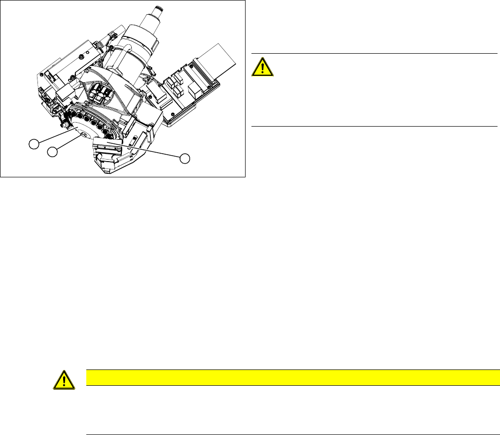
1. Silencer for holding circuit
2. Fastening screw [03005119-xx]
3. Lens system of component camera
CAUTION!
Camera
Make sure that you do not damage or contaminate the
camera lens system.
1
3
2
CAUTION
Installation instructions
► Carefully press the new silencer down, onto the holding circuit.
► Carefully retighten the screw manually (hand-tight only).
3 Service Work Conveyor
3.6 Replacing the Seal Disk on the Hold Circuit [03005120-xx]
26 Service Manual SIPLACE C&P20, C&P20A, C&P20M
3.6
3.6 Replacing the Seal Disk on the Hold Circuit [03005120-xx]
Replacing the Seal Disk on the Hold Circuit [03005120-xx]
Parts, equipment and tools
▪ Seal disk [03005120-xx]
▪ Tools for removing the head, if needed (see also the service manual for your machine)
Overview
Preparation
► Remove the head from the machine. For removal and installation details of the placement head, read
the service manual for your machine.
Removal
► Loosen the screw fastening the silencer and remove the silencer.
► Loosen the three screws fastening the holding circuit.
► Carefully lever the holding circuit off the locating pins and remove the seal disk . Make sure that the
O-ring is not damaged.
Installation
► Follow the removal instructions in reverse order for installation.
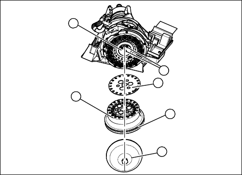
1. Silencer
2. Hold circuit
3. O-ring
4. Seal disk
5. 3 x fastening screws on the holding circuit
5
1
5
4
3
2
3 Service Work Conveyor
3.7 Replacing the Return Unit [03007696-xx]
Service Manual SIPLACE C&P20, C&P20A, C&P20M 27
3.7
3.7 Replacing the Return Unit [03007696-xx]
Replacing the Return Unit [03007696-xx]
Parts, equipment and tools
▪ Return unit [03007696-xx]
▪ Torque screwdriver 100-500 Ncm [03078400-xx]
▪ Tools for removing the head, if needed (see also the service manual for your machine)
Overview
Preparation
► Remove the head from the machine. For removal and installation details of the placement head, read
the service manual for your machine.
Removal
► Disconnect the power supply from the solenoid valve and the hose from the compressed air connec
-
tion.
► Loosen the two screws fastening the return unit and remove the complete return unit.
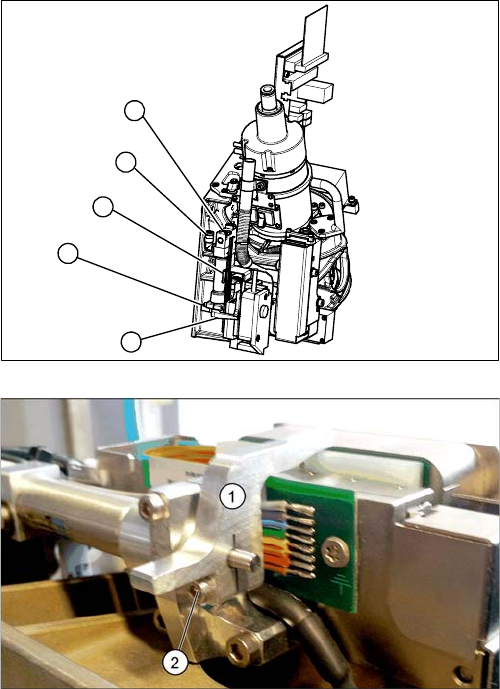
1. Solenoid valve
2. Compressed air connection
3. Return unit
4. 2x fastening screws for the return unit
5. Z axis driver
The return unit is installed on the Z axis and is responsi
-
ble for protecting the Z axis from damage, by moving it
into a safe area in the case of unexpected events (e.g.
power cuts or machine shutdown).
1. Z axis driver
2. Fastening screw for driver
2
3
5
4
1