00197465-01_SM_CP20-A-M_EN.pdf - 第52页
5 Settings 5.2 Optical Nozzle Query (Nozzle Scanning) 52 Service Manual SIPLACE C&P20, C&P20A, C&P20M 5.2 5 . 2 O p t ic a l N o z z le Q u e r y ( N o z z le S c a n n in g ) Optical Nozzle Query (Nozzle Sca…

5 Settings
5.1 Overview of Spare Parts and Settings for C&P20A
Service Manual SIPLACE C&P20, C&P20A, C&P20M 51
5
5 Settings
Settings
5.1
5.1 Overview of Spare Parts and Settings for C&P20A
Overview of Spare Parts and Settings for C&P20A
Description (spare part) Tools Values
Component Camera Calibration tool
Allen key
Measuring the digital component camera
Digital Vacuum Generator. CACCIA Firmware download possible
Read unit Z axis (not spare
part)
Feeler gauge 0.4 mm ▪ 0.4 mm between incremental encoder
and incremental scale
Complete Z drive
▪ Incremental encoder
▪ Linear motor
Allen key During assembly, press the Z drive against
the stops.
▪ Determine the zero point correction for Z
axis and star.
Z axis return unit Move the return unit actuator to its end stop,
so that the Z axis is in the top position and
the star can be rotated.
Light barrier Z axis down (not
spare part)
Test probe 1.0 mm Distance 1,0 mm
Component sensor Check function
Firmware download possible
Silencer 10 mm open-end
wrench
None
Vacuum holding circuit, com
-
plete
▪ Vacuum generator
▪ Silencer
▪ Special screw
10 mm open-end
wrench
Allen key
Segment with DP drive Nippers with plastic tips
Allen wrench
Settings: none; firmware download possible;
calibrate segment offset (top, bottom).
Star carrier, complete (not
spare part)
Allen key Determining the star and Z zero point cor
-
rection.
E/D transformer (collector ring)
assembly (for SIPLACE Ser
-
vice only)
Allen key Determining the Z and star zero point cor
-
rection.
5 Settings
5.2 Optical Nozzle Query (Nozzle Scanning)
52 Service Manual SIPLACE C&P20, C&P20A, C&P20M
5.2
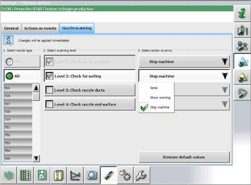
5.2 Optical Nozzle Query (Nozzle Scanning)
Optical Nozzle Query (Nozzle Scanning)
5.3
5.3 Calibration
Calibration
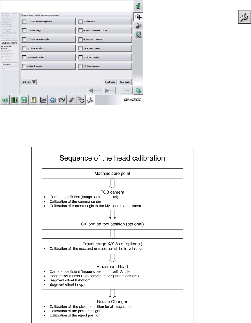
Overview
This calibration step first measures the component camera. This determines the relationship of "camera
pixel size to resolution of machine measuring system (X,Y)", the "camera center point in X and Y direc
-
tion" and the "torsion angle of the CCD sensor in the camera". This is following by determining the head
offset and the segment offsets for the top and bottom.
▪ Head offset: the head offset is the distance between the PCB camera and the nozzle (segment 1).
The target is a fixed value (X=0 and Y=
-
105 mm), to which an offset value (from the head calibration)
is added.
▪ Segment offset top: the top segment offset involves turning the calibration tool in the component
camera in 0, 90, 180 and 270° steps. The value determined is that of the rotating center of the nozzle
tip in relation to the component camera center in the X and Y direction.
▪ Segment offset bottom: the bottom segment offset involves recording and measuring the calibration
tool in the 0, 90, 180 and 270° positions. The value determined is that of the rotating center point of
the nozzle tip when the Z axis is extended in relation to the PCB camera. Segment 1 forms the ref
-
erence (X=0, Y=0) to the other segments.
The nozzle scan can be enabled or disabled in the soft
-
ware. Different scanning levels and the corresponding
actions for the errors in individual nozzle types can be de
-
fined.
5 Settings
5.3.1 Calibrating the Heads and Cameras 5.3 Calibration
Service Manual SIPLACE C&P20, C&P20A, C&P20M 53
5.3.1
5.3.1 Calibrating the Heads and Cameras
Calibrating the Heads and Cameras
5.3.2
5.3.2 Calibration Procedure (C&P, CPP, DLM)
Calibration Procedure (C&P, CPP, DLM)
C&P calibration procedure
► Switch over to the operator level Service (Customer).
► Switch over to the Service menu and select Ma
-
chine calibration or Automatic calibration (depending
on SW version).
► Select 8. Head and cameras and click on Next.
► On the next page, select the gantries on which the
heads to be calibrated are located and then click on
Next.
► The next step is to check the calibration conditions
(nozzle, calibration tool etc.). Follow the instructions
provided.
After this step, calibration will begin. All required interme
-
diate steps (head height etc.) will be performed automat
-
ically.