00197465-01_SM_CP20-A-M_EN.pdf - 第40页
3 Service Work Conveyor 3.11 Replacing the Component Sensor [03006742-xx] 40 Service Manual SIPLACE C&P20, C&P20A, C&P20M 3.11 3 . 1 1 R e p la c in g t h e C o m p o n e n t S e n s o r [ 0 3 0 0 6 7 4 2 - x…
3 Service Work Conveyor
3.10 Replacing and Setting the Jaws [03010313-xx]
Service Manual SIPLACE C&P20, C&P20A, C&P20M 39
Final Work:
Further installation is performed by following the above instructions in the reverse order. Proceed as fol
-
lows:
► Attach the two new dead indexing plates (not the ones you removed, these could be damaged). At
-
tach nozzles, if required.
► Remove the hose piece from the return unit.
► Refit the Z axis cover.
► Fit the remaining parts and install the head in the machine.
► Connect all cables and hoses.
► Switch the placement machine on.
► Determine the zero point correction value for the star and Z axes.
See also
5.4.3 Determining the zero point correction value for the star and Z axis from SW605.03.SP1 [ ➙ 57]
5.4.4 Determining the Zero Point Correction Value for the Star and Z Axis from SW705.04 [ ➙ 58]
3 Service Work Conveyor
3.11 Replacing the Component Sensor [03006742-xx]
40 Service Manual SIPLACE C&P20, C&P20A, C&P20M
3.11
3.11 Replacing the Component Sensor [03006742-xx]
Replacing the Component Sensor [03006742-xx]
Parts, equipment and tools
▪ Component sensor [03006742-xx]
▪ Torque screwdriver 100-500 Ncm [03078400-xx]
▪ Extension/straight TX20 [03073256-xx]
▪ Magnet removal plate C&P20A [03078491-xx]
▪ Tools for removing the head, if needed (see also the service manual for your machine)
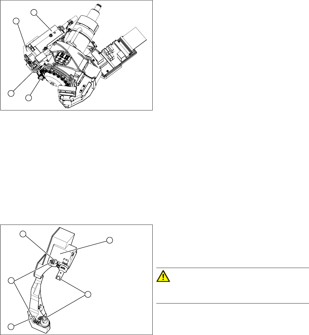
Overview
Preparation
► Remove the head from the machine. For removal and installation details of the placement head, read
the service manual for your machine.
Removal
► Remove the pressure control valve (4). This gives you access to the Z drive
► Remove the cover (2) on the Z axis and then remove the Z axis (3) with the return unit. (See also
"3.12 Replacing the Z Drive [03058631-xx]" [ ➙ 42])
► You can now access the component sensor (1).
► Unplug the electrical connection to the intermediate distributor. Remove any cable ties.
1. Component sensor
2. Z axis cover
3. Z axis with return unit
4. Pressure control valve
1
4
3
2
1. 2 x locking screws, behind: fastening screws
2. Lens system of transmitter and receiver unit
3. Complete component sensor
4. 2 x fastening screws
CAUTION!
Make sure that you do not damage or contaminate the
optical system of the transmitter and receiver unit.
4
4
1
3
2

3 Service Work Conveyor
3.11 Replacing the Component Sensor [03006742-xx]
Service Manual SIPLACE C&P20, C&P20A, C&P20M 41
► Loosen the two fastening screws (4) and remove the complete component sensor (3).
Installation
► Install the new component sensor. Tighten the fastening screws with a torque of 130 Ncm.
► Reconnect to the electricity system. Fasten the cable with cable ties.
► Fit the Z axis with return unit and the pressure control valve.
► Perform a reference run.
NOTICE
Do not separate the transmitter and receiver unit
The components of the transmitter and receiver unit are coordinated with one another. Only
loosen the two fastening screws, otherwise the component sensor will no longer function prop
-
erly.
NOTICE
Reference run
If the reference run fails, you will need to check the settings for the jaws on the Z drive.