00197465-01_SM_CP20-A-M_EN.pdf - 第69页
6 Description of the Circuit Boards 6.1 Intermediate distributor C&P20 [03002942-xx] Service Manual SIPLACE C&P20, C&P20A, C&P20M 69 Switch S1 The default switch sett ing is always p rinted in bold . Swit…
6 Description of the Circuit Boards
6.1 Intermediate distributor C&P20 [03002942-xx]
68 Service Manual SIPLACE C&P20, C&P20A, C&P20M
Dip switch S1 [03002942-09]
Dip switch S2 [03002942-09]
Further Information
V17 YE ON Potential difference between GND and
GND_VHS present
V18 YE ON Potential difference between GND and
GND_VHS present
V106 RD ON 24V+_VHS Error in the 24VDC power supply, VHS
Switch Status Signal name Description
S1.1 OFF CAN_ID CAN_ID signal for return unit deactivated
S1.2 ON CAN_TEST -
Switch Status Signal name Description
S2.1 OFF Q1 Do NOT bypass Q1
S2.2 ON Z_BOTTOM Light barrier Z bottom
LED Color Status Signal name Description
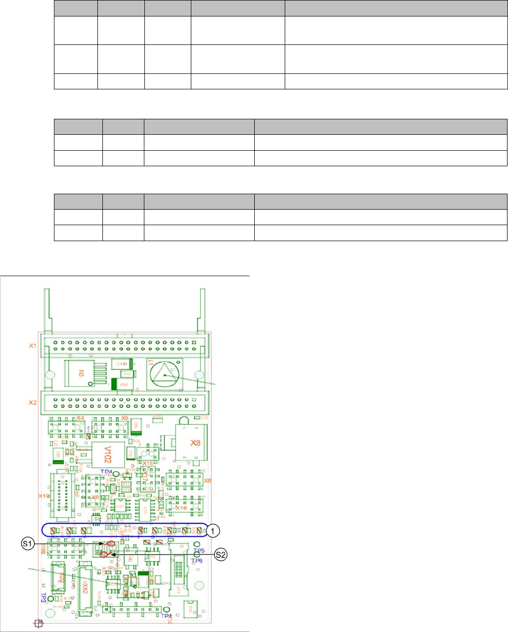
Intermediate distributor
The following supply voltages and signals are routed by
the intermediate distributor to the individual placement
head modules or to the head board:
1. LEDs show the operating voltages on the head and
the sensor states
▪ Connector X1, 40-pole: connected to connector X1
on the head adapter board
▪ Connector X2, 40-pole: connected to connector X2
on the head adapter board
▪ Connector X3: connection for the star motor
▪ Connector X4: connection for the star incremental en
-
coder
▪ Connector X6: connection for the Z axis incremental
encoder
▪ Connector X8: connection for the Z motor
▪ Connector X9: connection for the component sensor
▪ Connector X12: connection for pressure control valve
▪ Connector X14: test connector X14_3: +5 V/X14_4:
+15 V/X14_5: -15 V/X14_7:24 V for DP motors
▪ Connector X15: connection for return unit
▪ Connector X16: internal CAN bus C&P20A
6 Description of the Circuit Boards
6.1 Intermediate distributor C&P20 [03002942-xx]
Service Manual SIPLACE C&P20, C&P20A, C&P20M 69
Switch S1
The default switch setting is always printed in bold.
Switch S2
The default switch setting is always printed in bold.
LEDs - meanings
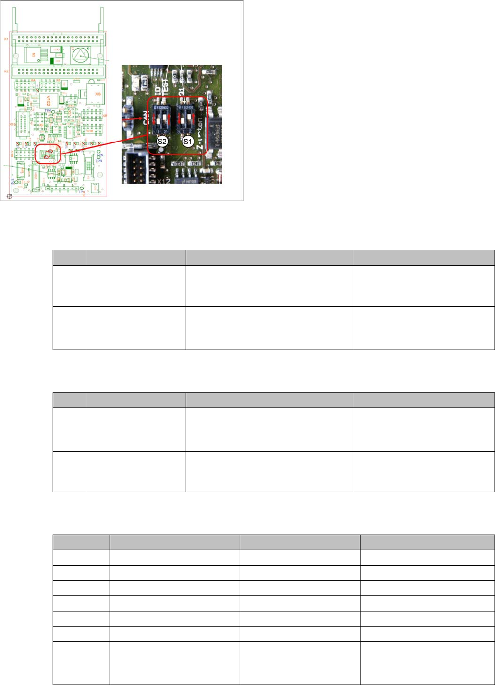
Intermediate distributor - position of DIP switch
S1, S2: DIP switch
No. Function Switch setting = 0 (open) Switch setting = 1 (closed)
S1.1 CAN test Normal operation: 1-wire head CAN
bus ready for operation with mother
-
board only
Test mode: operation without
motherboard possible
S1.2 CAN ID switchover -
pressure control valve
CAN ID active for pressure control
valve
0x6B0
CAN ID for pressure control
valve 0x6B8 (test mode)
No. Function Switch setting = 0 (open) Switch setting = 1 (closed)
S2.1 Z bottom sensor:
switch on LED
LED is only switched on during opera
-
tion
Switched on
LED always on (test mode e.g.
for detection of nozzle suspen
-
sion with oscilloscope)
S2.2 Z bottom sensor: acti
-
vating LED in clocked
mode
LED is clocked during
operation
LED is always switched on dur
-
ing operation
No. Function On OFF
D3 +5V Present Not present
D4 Z bottom Triggered Not triggered
D5 Z bottom reset Reset Not reset
D6 +15V Present Not present
D7 +24 V_IN
D8 -15V Present Not present
V2 Z return valve Activated (bottom) Not activated (top)
V11 Enable pressure control
valve
Error pressure control
valve
Pressure control valve OK

6 Description of the Circuit Boards
6.1 Intermediate distributor C&P20 [03002942-xx]
70 Service Manual SIPLACE C&P20, C&P20A, C&P20M
Test points
Test connector X14
V14 +24V Present Not present
V15 +24 V_DP Switched on Switched off
V16/17 Voltage GND
No. Function
TP1 GND
TP3 Voltage pressure signal, internal pressure control valve
TP4 Output voltage I/U converter Z bottom
TP5 Z bottom
TP6 Z top/Z bottom - reset
Pin Signal
1CAN_RX
2GND
3+5V
4+15V
5-15V
6 X2_11
724V_DP
8 Z top/Z bottom - reset
No. Function On OFF