00197465-01_SM_CP20-A-M_EN.pdf - 第53页
5 Settings 5.3.1 Calibrating the Heads and Cameras 5.3 Calibration Service Manual SIPLACE C&P20, C&P20A, C&P20M 53 5.3.1 5 . 3 . 1 C a lib r a t in g t h e H e a d s a n d C a m e r a s Calibrating the Heads …
5 Settings
5.2 Optical Nozzle Query (Nozzle Scanning)
52 Service Manual SIPLACE C&P20, C&P20A, C&P20M
5.2
5.2 Optical Nozzle Query (Nozzle Scanning)
Optical Nozzle Query (Nozzle Scanning)
5.3
5.3 Calibration
Calibration
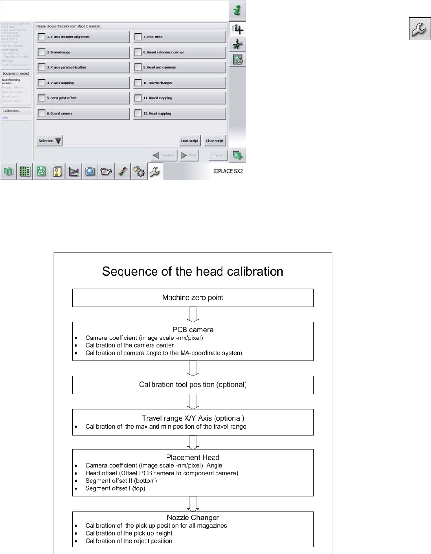
Overview
This calibration step first measures the component camera. This determines the relationship of "camera
pixel size to resolution of machine measuring system (X,Y)", the "camera center point in X and Y direc
-
tion" and the "torsion angle of the CCD sensor in the camera". This is following by determining the head
offset and the segment offsets for the top and bottom.
▪ Head offset: the head offset is the distance between the PCB camera and the nozzle (segment 1).
The target is a fixed value (X=0 and Y=
-
105 mm), to which an offset value (from the head calibration)
is added.
▪ Segment offset top: the top segment offset involves turning the calibration tool in the component
camera in 0, 90, 180 and 270° steps. The value determined is that of the rotating center of the nozzle
tip in relation to the component camera center in the X and Y direction.
▪ Segment offset bottom: the bottom segment offset involves recording and measuring the calibration
tool in the 0, 90, 180 and 270° positions. The value determined is that of the rotating center point of
the nozzle tip when the Z axis is extended in relation to the PCB camera. Segment 1 forms the ref
-
erence (X=0, Y=0) to the other segments.
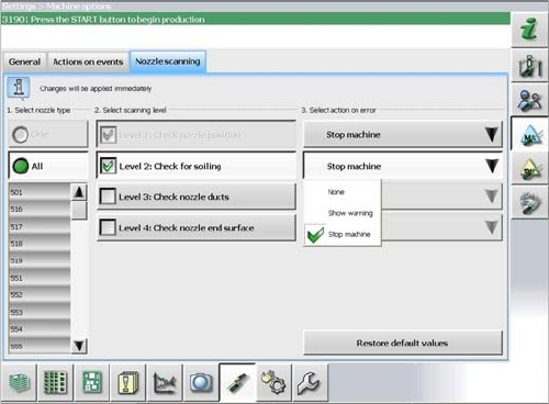
The nozzle scan can be enabled or disabled in the soft
-
ware. Different scanning levels and the corresponding
actions for the errors in individual nozzle types can be de
-
fined.
5 Settings
5.3.1 Calibrating the Heads and Cameras 5.3 Calibration
Service Manual SIPLACE C&P20, C&P20A, C&P20M 53
5.3.1
5.3.1 Calibrating the Heads and Cameras
Calibrating the Heads and Cameras
5.3.2
5.3.2 Calibration Procedure (C&P, CPP, DLM)
Calibration Procedure (C&P, CPP, DLM)
C&P calibration procedure
► Switch over to the operator level Service (Customer).
► Switch over to the Service menu and select Ma
-
chine calibration or Automatic calibration (depending
on SW version).
► Select 8. Head and cameras and click on Next.
► On the next page, select the gantries on which the
heads to be calibrated are located and then click on
Next.
► The next step is to check the calibration conditions
(nozzle, calibration tool etc.). Follow the instructions
provided.
After this step, calibration will begin. All required interme
-
diate steps (head height etc.) will be performed automat
-
ically.
5 Settings
5.4 Zero Point Correction for the Star and Z Axis 5.4.1 Transfer head specific data to the machine data after manual head
54 Service Manual SIPLACE C&P20, C&P20A, C&P20M
5.4
5.4 Zero Point Correction for the Star and Z Axis
Zero Point Correction for the Star and Z Axis
5.4.1
5.4.1 Transfer head specific data to the machine data after manual head exchange
Transfer head specific data to the machine data after manual head exchange
Transfer head specific data manually
Precondition: The head needs to have been referenced (star and Z axis).
NOTICE
Fast Head Exchange
If a head exchange is carried out with the FHE function the head specific data will be automat
-
ically transferred to the machine data.
► Switch over to operator level SIPLACE (customer).
► Select Manual operations (Check sensors and func
-
tions) --> Check sensors and functions of spe
-
cific components .
► Select the relevant head.
► Select Z axis.
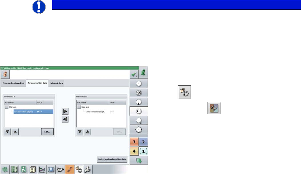
► Select Zero correction data.
► In the Head EEPROM section, select the relevant pa
-
rameters, then click on Edit and enter the corre
-
sponding value.
► Use the arrow button of the head EEPROM to trans
-
fer the data to the machine data.
► After correcting the parameters, select Write head
and machine data.
► Repeat these settings for the star axis.