00197465-01_SM_CP20-A-M_EN.pdf - 第58页
5 Settings 5.4 Zero Point Correction for the Star and Z Axis 5.4.4 Determin ing the Zero Point Correction Value for the Star and Z Axis fro m 58 Service Manual SIPLACE C&P20, C&P20A, C&P20M 5.4.4 5 . 4 . 4 D …
5 Settings
5.4.3 Determining the zero point correction value for the star and Z axis from SW605.03.SP1 5.4 Zero Point Correction for the Star and Z Axis
Service Manual SIPLACE C&P20, C&P20A, C&P20M 57
5.4.3
5.4.3 Determining the zero point correction value for the star and Z axis from SW605.03.SP1
Determining the zero point correction value for the star and Z axis from SW605.03.SP1
The menu for determining the zero point correction value is only accessible with the service password
(customer)!
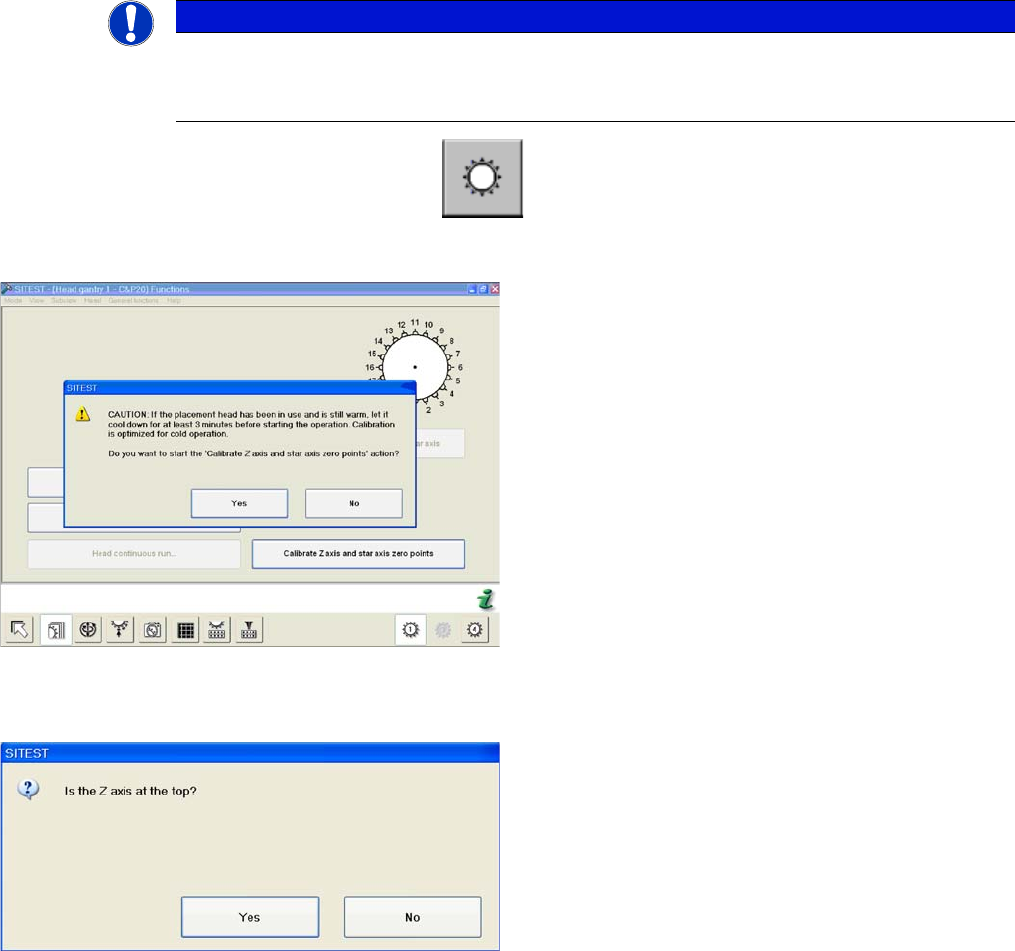
► Start SITEST --> Head Functions .
► Click on the Calibrate Z axis and star axis zero points button.
NOTICE
Calibrate Z axis and star axis zero points
The function Calibrate zero point correction should be carried out after service work to the
C&P20 head. (e.g. Z axis, component sensor replacement)
Calibrating the Z axis and star axis zero point correction
values
► You may need to wait 3 minutes, until the head has
cooled down.
► Confirm the question shown with YES.
Z axis up request for confirmation
► Check the position of the Z axis and click on YES.
5 Settings
5.4 Zero Point Correction for the Star and Z Axis 5.4.4 Determining the Zero Point Correction Value for the Star and Z Axis from
58 Service Manual SIPLACE C&P20, C&P20A, C&P20M
5.4.4
5.4.4 Determining the Zero Point Correction Value for the Star and Z Axis from SW705.04
Determining the Zero Point Correction Value for the Star and Z Axis from SW705.04
The menu for determining the zero point correction value is only accessible with the service password
(customer)!
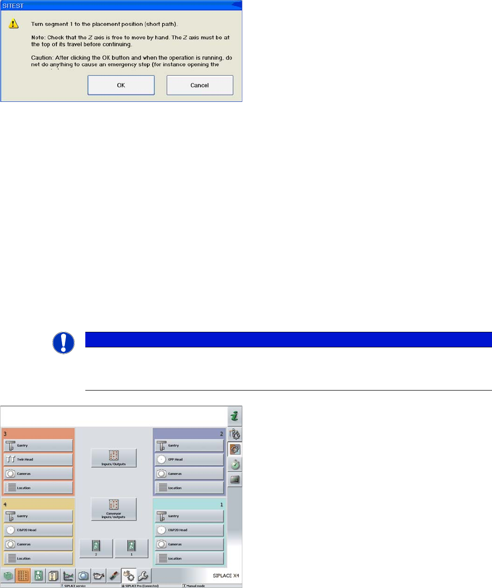
Turning segment 1 manually into the placement position
► Switch the Z axis off at the axis card.
► Rotate the star with segment 1 by the shortest route,
into the placement position.
► Open the cover.
► Rotate the star until segment 6 can be seen through
the service opening. Segment 1 is then in the pick
and place position.
► Move segment 1 downwards with the help of the re
-
turn unit.
► When the segment is moved out (Z axis down), check
that the segment ball bearing is in the center of the
jaws.
► Close the cover.
► Press the Start button on the machine.
► Click on OK on your screen.
The calibration process will begin and the new Z axis and
star axis zero point correction values will be stored in the
Achs_ver.ma and on the head EPROM.
NOTICE
Calibrate Z axis and star axis zero points
The function Calibrate zero point correction should be carried out after service work to the
C&P20 head. (e.g. when replacing the Z axis or component sensor)
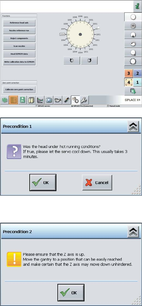
► Log in as "Service (customer)".
► Click on the Check sensors and functions button.
5 Settings
5.4.4 Determining the Zero Point Correction Value for the Star and Z Axis from SW705.04 5.4 Zero Point Correction for the Star and Z Axis
Service Manual SIPLACE C&P20, C&P20A, C&P20M 59
► Select the relevant head.
► Click on the Calibrate Z axis and star axis zero points
button.
Calibrating the Z axis and star axis zero point correction
values
► You may need to wait 3 minutes, until the head has
cooled down.
► Acknowledge the question shown with OK.
Z axis up request for confirmation
► Check the position of the Z axis and click on OK.