00197465-01_SM_CP20-A-M_EN.pdf - 第36页
3 Service Work Conveyor 3.10 Replacing and Setting the Jaws [03010313-xx] 36 Service Manual SIPLACE C&P20, C&P20A, C&P20M Setting the jaws Fit the setting gauge as follows. Moving the Z axis arms out ► R o t …
3 Service Work Conveyor
3.10 Replacing and Setting the Jaws [03010313-xx]
Service Manual SIPLACE C&P20, C&P20A, C&P20M 35
Dismantling the dead indexing plate
1. 2 segments without nozzles or dead indexing plate
► Remove the nozzles and dead indexing plates from
two neighboring segments.
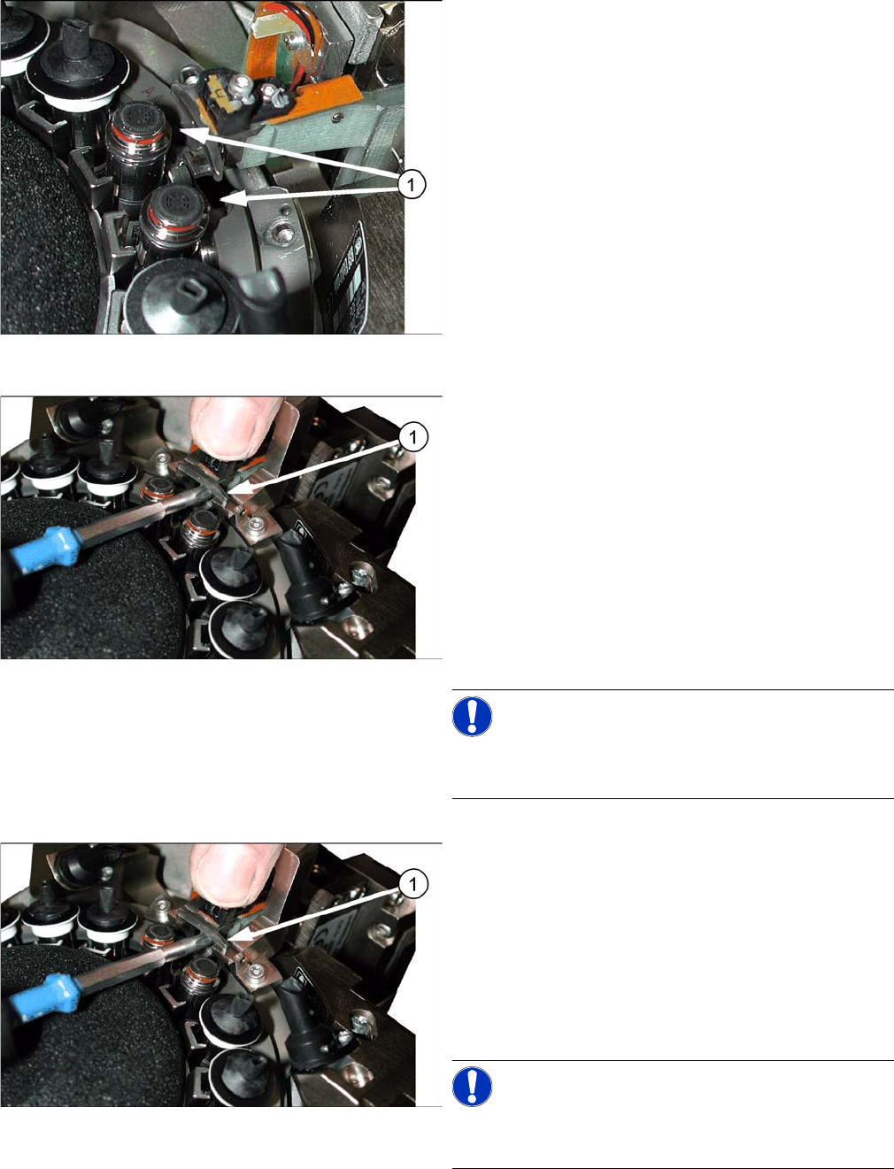
Screw fastening the jaws
Perform the following steps if you want to replace the
jaws (and then set them).
► Loosen the screw (1) fastening the jaws and then pull
the jaws out of the head.
► Insert the new jaws. Carefully tighten the screw fas
-
tening the jaws, so that the jaws can still be moved on
the arm of the Z axis (can be moved to the left and
right).
Do not fit the gauge yet!
► Clean the raceway contact surface and the setting
gauge with a lint-free cloth.
NOTICE!
Always clean the contact surfaces before fitting the set
-
ting gauge!
Screw fastening the jaws
Perform the following steps if you want to set the jaws
without replacing them.
► Carefully loosen the screw (1) fastening the jaws, so
that the jaws can still be moved on the arm of the Z
axis (can be moved to the left and right).
Do not fit the gauge yet!
► Clean the raceway contact surface and the setting
gauge with a lint-free cloth.
NOTICE!
Always clean the contact surfaces before fitting the set
-
ting gauge!
3 Service Work Conveyor
3.10 Replacing and Setting the Jaws [03010313-xx]
36 Service Manual SIPLACE C&P20, C&P20A, C&P20M
Setting the jaws
Fit the setting gauge as follows.
Moving the Z axis arms out
► Rotate the star so that the jaws/arms of the Z axis are
centered between the two segments, without dead in
-
dexing plates.
► Move the Z axis without segment out.
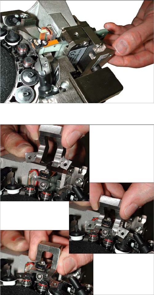
Fitting the jaw setting gauge
► Place the jaw setting gauge on the raceway, ensuring
that the jaws lie flat on the contact surfaces.
Press the jaw setting gauge against the holes drilled
in the raceway, so that the centering pins engage with
the relevant holes.
3 Service Work Conveyor
3.10 Replacing and Setting the Jaws [03010313-xx]
Service Manual SIPLACE C&P20, C&P20A, C&P20M 37
Set the jaws as follows:
► Make sure that the Z axis is located between the two segments without dead indexing plates and
that you can see the Phillips screw.
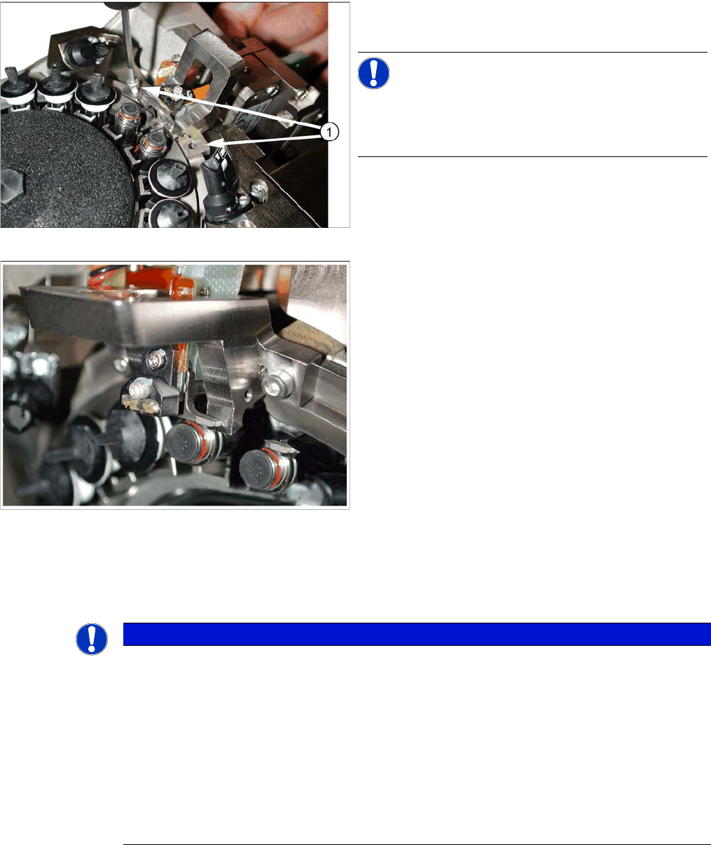
Fastening the jaw setting gauge
Jaw setting gauge on C&P20 head
► Fasten the gauge with the screws (1) from the service
kit (M2.5x12 mm).
NOTICE!
Do not use the original raceway screws, to fix the jaw set
-
ting gauge! These are too short and could damage the
thread!
NOTICE
Troubleshooting:
► If side stopper (stop pin) of the gauge presses against the jaws so that these can not be
moved, proceed as follows:
if it is not possible to push the 0.04 feeler gauge between the jaws and the stop pin of the
gauge, make sure that the jaws lie flat against contact surfaces (2a) and (2b) of the gauge
(see overview picture at the beginning of this chapter.)
► If you are unable to press the jaws against the side stopper (stop pin) of the gauge, proceed
as follows:
push the jaws as far as possible towards the stop pin. Do not push the jaws with force
against the stop pin of the gauge.