Printer 600 Board Support Tooling Module.pdf - 第13页
%2$5'68 33257722/,1* 02'8/( )250)/(; 722/,1* Chapter Issue 2 May 03 Technical Reference Manual 19.13 Air Supply W ARNING COMPRESSED AIR. COMP RESSED AIR SHOULD NEVER IM PINGE UPON THE BODY . PORTS, PIPE S, …
19.12 Technical Reference Manual Chapter Issue 2 May 03
%2$5'6833257722/,1*02'8/(
)250)/(;722/,1*
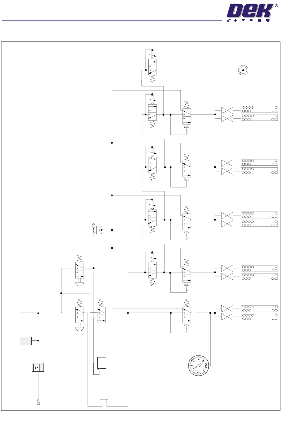
Pneumatic Schematic
Mains Air
Connection
5 bar (min)
To
Pneumatic
Manifold
Filter
Regulator
Assembly
Pressure
Sensor
Ball Valves
Tooling Modules
P
A
R
P
A
R
P
A
R
P
A
R
2
1
3
2
1
3
2
1
3
1
2
3
4
5
6
7
8
9
10
Pneumatic Indicator
Air Pilot
Operated Valves
2
1
3
tttt
P
A
R
Pneumatic Timers
Zn
Zn
Zn
Zn
Zn
2
1
3
t
OR
NOT
Vacuum Ejector
Operator Switch
(Non-Latching Manual Valve)
Reset Switch
(Non-Latching Manual Valve)
13
2
2
2
2
3
3
3
3
1
1
1
1
2
3
1
Yes Gate
Pressure/Vacuum Gauge
%2$5'6833257722/,1*02'8/(
)250)/(;722/,1*
Chapter Issue 2 May 03 Technical Reference Manual 19.13
Air Supply
WARNING
COMPRESSED AIR. COMPRESSED AIR SHOULD NEVER IMPINGE UPON THE
BODY. PORTS, PIPES, ETC MUST NEVER BE BLOCKED BY HAND. BEFORE
CONNECTING ANY PNEUMATIC EQUIPMENT TO A COMPRESSED AIR SUPPLY,
ALL MOUNTINGS, FITTINGS, PIPEWORK AND ELECTRICAL CONNECTIONS
SHOULD BE REMOVED FOR SAFETY. NO PIPEWORK ALTERATIONS OR
REMOVAL OF FITTINGS SHOULD BE ATTEMPTED WITH AIR SUPPLIES
CONNECTED.
Air Pressure For the FormFlex tooling to operate correctly the system requires air at the
following pressure:
• Minimum pressure - 5.0 bar
• Maximum pressure - 8.0 bar
Air Quality The air should be to quality class 2.3.3, where:
2 (dirt) = 1 micron
3 (water) = -20°C pressure dewpoint
3 (oil) = 1mg/m³
Tooling Module
WARNING
HARMFUL SUBSTANCES. CLEANING WIPES AND CLEANING SOLUTIONS MAY
CONTAIN SUBSTANCES HAZARDOUS TO HEALTH. OBSERVE ALL
MANUFACTURERS’ HEALTH AND SAFETY GUIDELINES. ALWAYS WEAR
APPROVED PROTECTIVE CLOTHING WHEN CLEANING THE MACHINE.
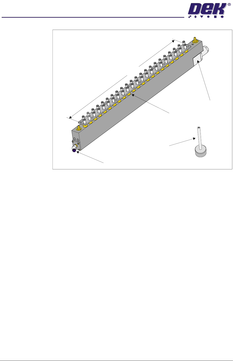
The FormFlex tooling system consists of 6 tooling modules, additional tooling
modules are available up to a maximum of 10 modules. Overall dimensions of
each module is 544mm x 25mm with a unit height of 66mm. The module is
connected to the manifold assembly mounted on the manual tooling plate. The
front module has dowel registration fitted and all the modules are held magnet-
ically to the manual tooling plate.
Pin Array Assembly The pin array assembly houses the 44 x 6mm diameter FormFlex pins at a
staggered pitch of 20mm and the fluid cut-off valve. The pin array assembly is
connected to the sequencer and peripherals assembly via the manifold assem-
bly. Each FormFlex pin is fitted with a replaceable graphite impregnated
polyurethane cap enabling Formflex to fully support brittle components and to
facilitate the electrostatic discharge properties of the unit.
Fluid Cut-off Valve The fluid cut-off valve controls the fluid flow to the FormFlex tooling pins. Once
the pins have conformed to the board, component or stencil the valve seals the
fluid supply to the channel beneath the FormFlex pins locking the pins in
position.
Cut-Off Valve
Override Pin
The cut-off valve override pin is used to release sticky cut-off valve stems either
causing the FormFlex pins to remain fully raised or fully lowered. One pin is
supplied with each FormFlex tooling set, (for further details see Fault Finding
later in this chapter).
19.14 Technical Reference Manual Chapter Issue 2 May 03
%2$5'6833257722/,1*02'8/(
)250)/(;722/,1*
Figure 19-10 Tooling Module
Pneumatic
Sequencer and
Peripherals
Assembly
The assembly is fitted to the sequencer block and logic plate which is secured
to the left hand side of the central rear upright of the lower frame of the printer,
and connected to the printer air supply via the operator interface. Mounted on
this panel are the components used to control the sequence of raising FormFlex
pins and produce vacuum to the pins. This panel routes pneumatic pressure
from the operator interface to the manifold assembly.
Pin Array Assembly
Fluid Cut Off Valve
Pneumatic Connection
436mm
(Outside of Pins)
Cut-Off Valve Override Pin