Printer 600 Board Support Tooling Module.pdf - 第24页
19.24 Technical Reference Manual Chapter Issue 2 May 03 %2$5'6 833257722/,1* 02'8/( )250)/(;7 22/,1* 1 1. Secure the pipes with a ca ble tie att ached to the mount above the rising t able home vane. 12. Con…
%2$5'6833257722/,1*02'8/(
)250)/(;722/,1*
Chapter Issue 2 May 03 Technical Reference Manual 19.23
Replacement Procedures
Fitting FormFlex Tooling
WARNING
COMPRESSED AIR. COMPRESSED AIR SHOULD NEVER IMPINGE UPON THE
BODY. PORTS, PIPES, ETC MUST NEVER BE BLOCKED BY HAND. BEFORE
CONNECTING ANY PNEUMATIC EQUIPMENT TO A COMPRESSED AIR SUPPLY,
ALL MOUNTINGS, FITTINGS, PIPEWORK AND ELECTRICAL CONNECTIONS
SHOULD BE REMOVED FOR SAFETY. NO PIPEWORK ALTERATIONS OR
REMOVAL OF FITTINGS SHOULD BE ATTEMPTED WITH AIR SUPPLIES
CONNECTED.
WARNING
BOARD CLAMPS. EXTREME CARE MUST BE EXERCISED WHEN WORKING IN
THE TOOLING AREA OF THE MACHINE TO AVOID INJURY. THE FOILS ON THE
FRONT AND REAR BOARD CLAMPS ARE VERY SHARP.
1. From the Run menu select Setup.
2. Select Change Tooling.
3. Select Full Width.
4. Power down the machine.
5. Ensure the front FormFlex tooling module has two registration dowels fitted
to the base of the unit. Locate the dowels in the holes in the front edge of
the manual tooling plate.
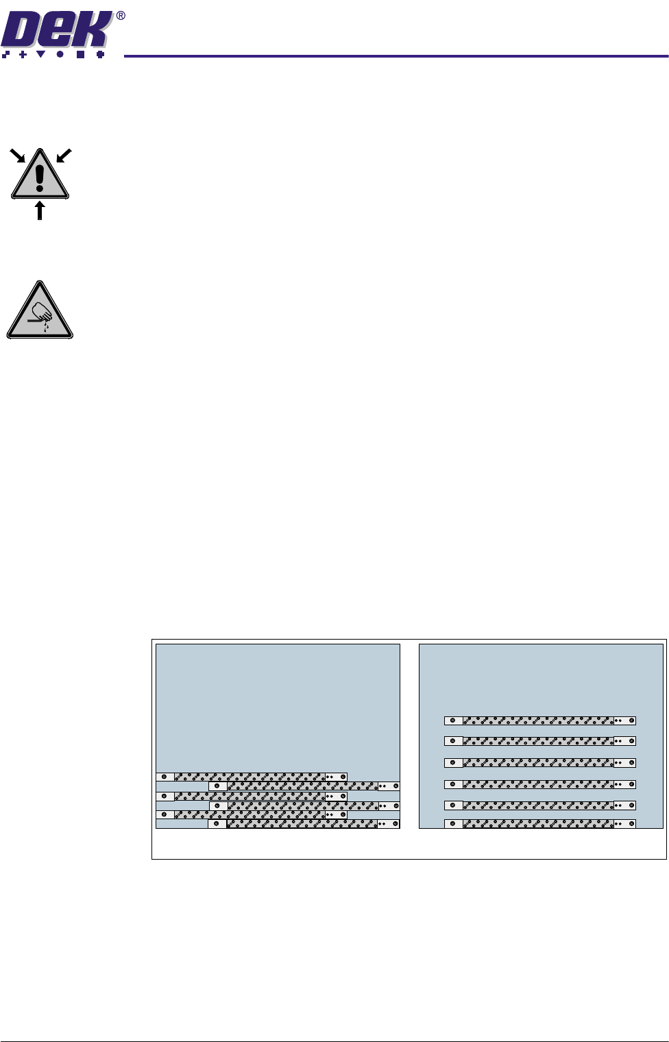
6. The remaining tooling modules can be configured to suit the product to be
printed. The first five modules are to be orientated with the pneumatic
connection to the right and the sixth and any additional modules are to be
orientated with the pneumatic connection to the left. The tooling modules
can be staggered in the X axis and/or spread evenly in the Y axis to fully
support the product to be printed (see figure below for examples).
7. Place the manifold assembly to the rear of the tooling plate.
8. Gain access to the rear of the machine.
9. Identify the five 4mm diameter output pipes from the sequencer and periph-
erals assembly.
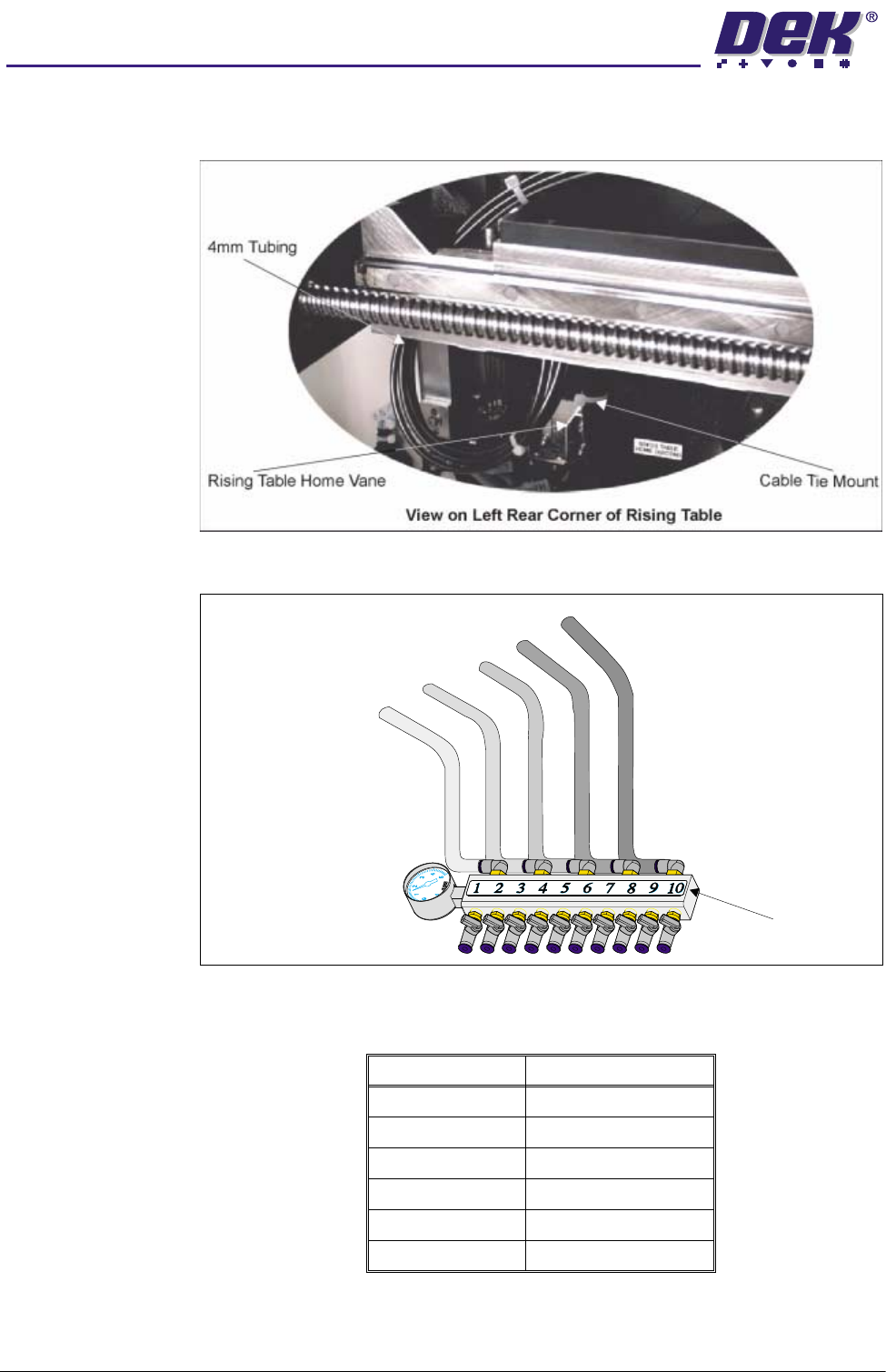
10.Route the pipes through the left hand hole of the rising table casting to the
manifold assembly. Ensure a loop of tubing for each pipe is fed up into the
web of the rising table casting above the rising table home vane.
Plan View on Manual Tooling Plate
6
6
5
5
4
4
3
3
2
2
11
19.24 Technical Reference Manual Chapter Issue 2 May 03
%2$5'6833257722/,1*02'8/(
)250)/(;722/,1*
11. Secure the pipes with a cable tie attached to the mount above the rising table
home vane.
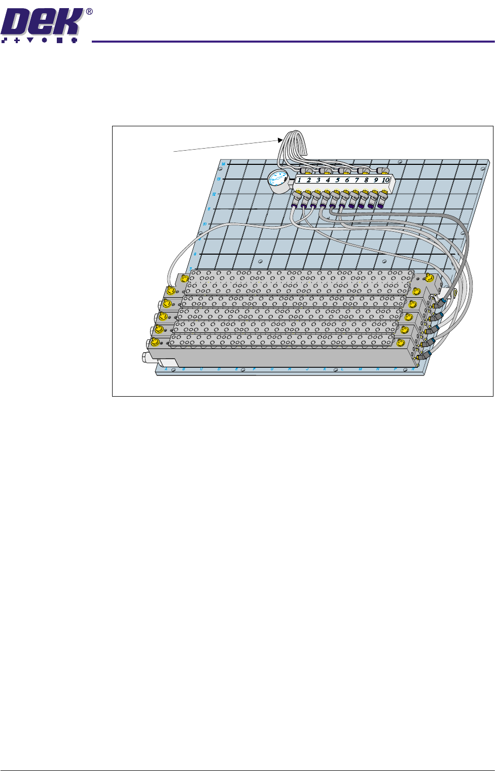
12.Connect the pipes to the manifold assembly (see diagram below).
13.Connect 4mm diameter tubing from the manifold assembly to the tooling
modules (see table and diagram below).
Module Number Manifold Connection
19/10
25/6
31
42
57/8
63/4
Pipe 1 From Sequencer
Pipe 2 From Sequencer
Pipe 3 From Sequencer
Pipe 4 From Sequencer
Pipe 5 From Sequencer
Manifold Assembly
%2$5'6833257722/,1*02'8/(
)250)/(;722/,1*
Chapter Issue 2 May 03 Technical Reference Manual 19.25
NOTE
If only five tooling modules are utilized, do not use manifold connections 1
or 2.
14.Secure the tubing with a cable tie attached to a magnetic cable tie mount.
Ensure the tubing does not foul the moving rail.
15.Power up the machine and select Board Width.
16.Carry out FormFlex Pin Pressure procedure in Adjustments and Settings
section of this chapter.
17.Carry out FormFlex Setup in the Machine Programming chapter of the User
manual.
Plan View on Manual Tooling Plate
4mm Tubing From
Pneumatic
Control/Sequencer Panel