Printer 600 Board Support Tooling Module.pdf - 第18页
19.18 Technical Reference Manual Chapter Issue 2 May 03 %2$5'6 833257722/,1* 02'8/( )250)/(;7 22/,1* Manifold Assembly The manifol d assembly co ntains ten ball valves al lowing indivi dual connect i on of …
%2$5'6833257722/,1*02'8/(
)250)/(;722/,1*
Chapter Issue 2 May 03 Technical Reference Manual 19.17
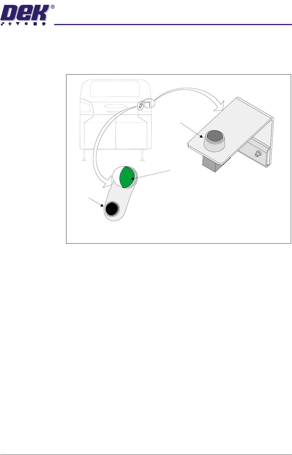
Operator Interface The operator interface comprises the following two assemblies:
• Operator Switch and Indicator Assembly
• Reset Switch Assembly
Figure 19-13 Operator Interface
Operator Switch &
Indicator Assembly
This assembly is fitted externally to the machine covers enabling immediate
access to the operator switch and a visual indication of position of the FormFlex
pins. The operator switch is a push button non latching pneumatic valve used
by the operator to raise the FormFlex pins during tooling setup. The pneumatic
indicator displays after the last pneumatic timer valve has operated, giving an
indication that all FormFlex pins have risen.
Reset Switch
Assembly
The reset switch assembly is fitted internally under the front printhead cover.
Operation of this push button non latching valve lowers the FormFlex pins thus,
resetting the FormFlex tooling for another product.
Reset Switch Assembly
(Internal)
Operator Switch & Indicator Assembly
(External)
Reset Switch
Pneumatic Indicator
Operator Switch
19.18 Technical Reference Manual Chapter Issue 2 May 03
%2$5'6833257722/,1*02'8/(
)250)/(;722/,1*
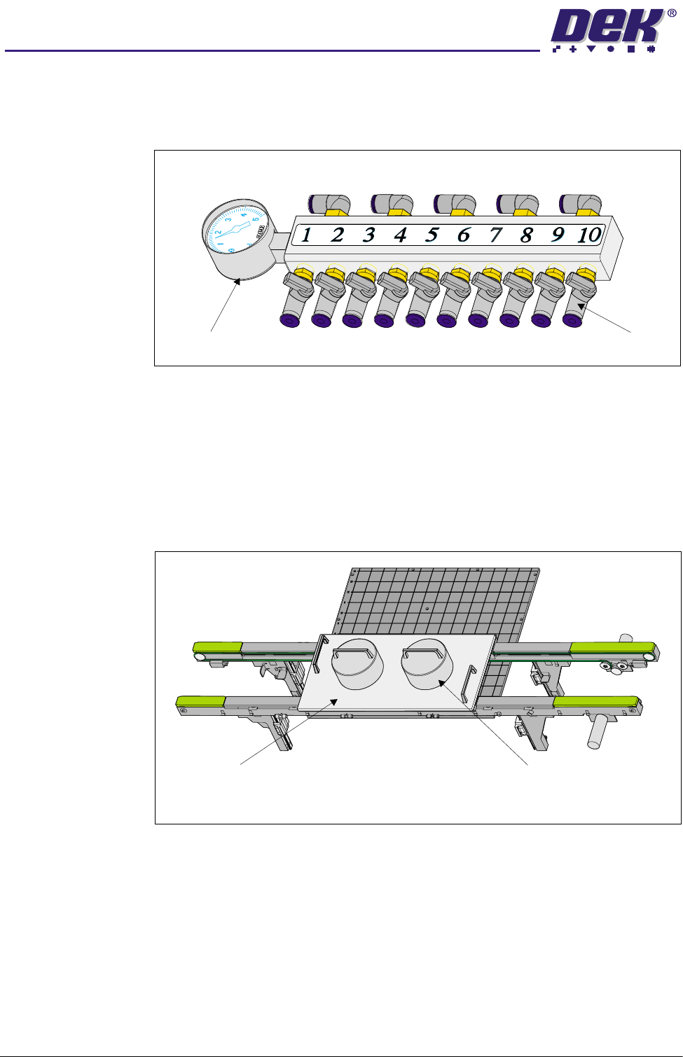
Manifold Assembly The manifold assembly contains ten ball valves allowing individual connection
of up to ten tooling modules. Fitted to the left hand end of the manifold assembly
is a -1 to +5 bar pressure/vacuum gauge, used as an aid to fault finding.
Figure 19-14 Manifold Assembly
Setup Plate and
Weights
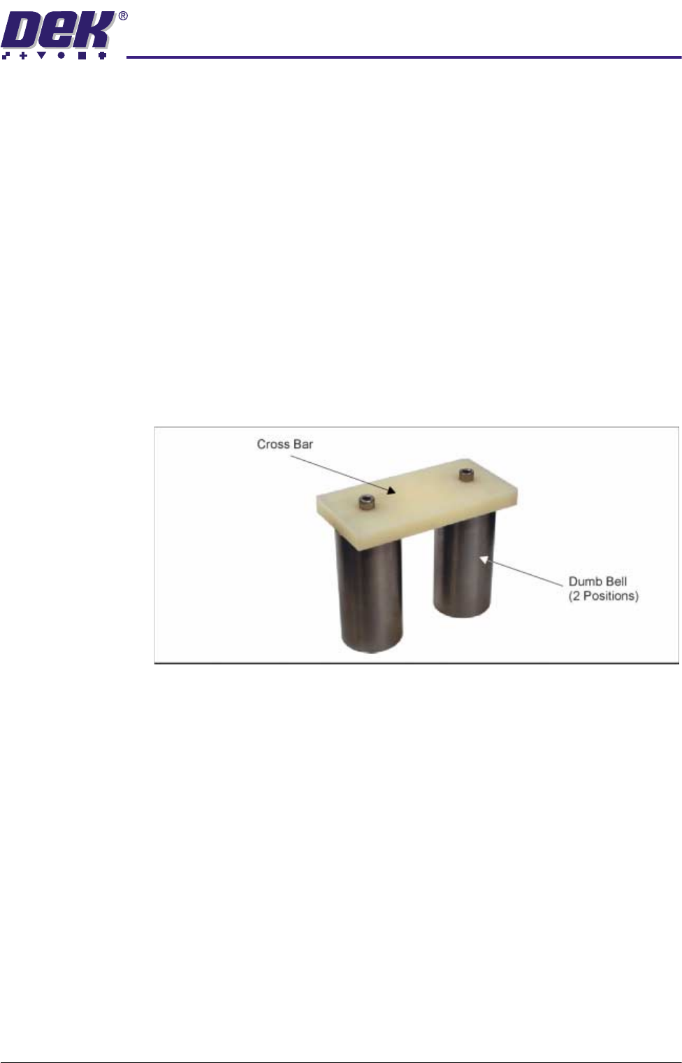
The FormFlex setup plate and weights are utilized during tooling setup to
ensure the FormFlex pins conform to the product profile. It consists of an
aluminium base plate and 6kg weights.
The plate is positioned centrally over the tooling modules and rails, the weights
are placed on the plate centrally in the Y axis and one third of the plate length
in the X axis.
Figure 19-15 Setup Plate and Weights
Pressure Gauge
Ball Valves
Setup Plate Weight (in 2 positions)
Plan View on Rails & Manual Tooling Plate
%2$5'6833257722/,1*02'8/(
)250)/(;722/,1*
Chapter Issue 2 May 03 Technical Reference Manual 19.19
Setting Weight
Assembly
The setting weight assembly is used to verify the FormFlex pin pressure is set
to approximately 250gms on the following occasions:
• After Installation
• Validate pressure when required
The unit is constructed from a pair of solid cylindrical metal dumb-bells secured
to a plastic cross bar by two cap headed screws. The weight of the assembly
is 1.25kg ±0.01.
The unit is placed over a tooling module, the cross bar covers an area of five/
six FormFlex pins. The system is operated, if the unit is raised off the tooling
plate by the six FormFlex pins, the combined pin pressure is greater than
1.25kg. Hence, each pin pressure is greater than 208gms.
If the unit is placed over an area of five FormFlex pins and the system is
operated and the FormFlex pins fail to raise the setting weight assembly, the
combined pin pressure is less than 1.25kg. Hence, each pin pressure is less
than 250gms.
Figure 19-16 Setting Weight Assembly