Printer 600 Board Support Tooling Module.pdf - 第4页
19.4 Technical Reference Manual Chapter Issue 2 May 03 %2$5'6 833257722/,1* 02'8/( 9$&880 %2;722/,1* V ACUUM BOX TOOLING The vacuum box is manufactured to the same height as the magnetic pins, ie 81mm,…
%2$5'6833257722/,1*02'8/(
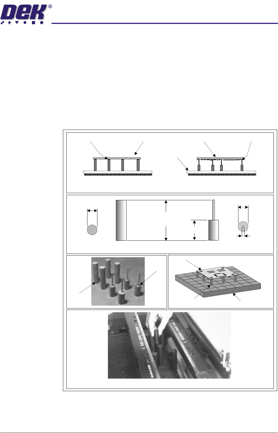
0$*1(7,&68332573,//$56
Chapter Issue 2 May 03 Technical Reference Manual 19.3
MAGNETIC SUPPORT PILLARS
The magnetic support pillars are positioned on the manual tooling plate by the
operator. These pillars can be positioned anywhere under the board to provide
board support.
Two types of support pillar are provided:
• Standard flat-top pillars (19mm) for supporting boards which are not
populated on the underside.
• Pin-top pillars (4mm) for supporting boards which are populated on the
underside. The pins are positioned so that they fit between the compo-
nents on the underside of the board.
Figure 19-2 Magnetic Support Pillars
Fitment of Magnetic Pillars to Table
Flat-top Pillars used on
Unpopulated Board
Tooling Plate
Pin-top Pillars used on
Populated Board
Populated BoardFlat-top Pillars Pin-top PillarsUnpopulated Board
Pin-top
Pillars
Flat-top
Pillars
Board
Magnetic Pillars
Tooling Plate
19mm
81mm
(nominal)
38mm
19mm Dia.
4mm Dia.
Flat-top Pillar Dimensions
Pin-top Pillar Dimensions
19.4 Technical Reference Manual Chapter Issue 2 May 03
%2$5'6833257722/,1*02'8/(
9$&880%2;722/,1*
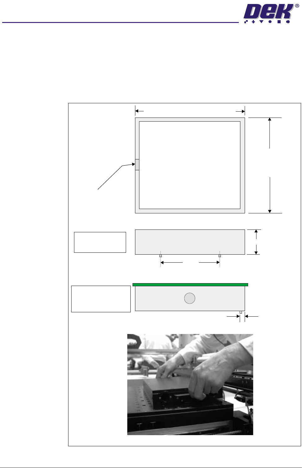
VACUUM BOX TOOLING
The vacuum box is manufactured to the same height as the magnetic pins, ie
81mm, irrespective of the thickness of the board being printed. The vacuum
boxes can be constructed without top or bottom plates to allow for additional pin
support of the board. Provision for machining of top plates to accommodate
underside components is available. The box is located on the table by means
of dowels.
Figure 19-3 Vacuum Box Tooling
Nominal Board Length -
( overhang of board, each end)
4mm
2mm
Plan View of Vacuum Box
Nominal Board
Width -
( overhang
of board, each end)
12mm
6mm
36mm Vacuum Hole
Insert Magnetic Pins as Required
Vacuum Box Fitted to the Machine Table (Left Side View)
Front View of Vacuum Box
81mm
80mm
+0.00mm
-0.05mm
NOTE
2 Front Dowel Pins
( diameter)3mm
Left Side View of Vacuum Box View of Vacuum Box
2.5mm
NOTE
View showing board
positioned on Vacuum
Box
%2$5'6833257722/,1*02'8/(
08/7,)/(;722/,1*
Chapter Issue 2 May 03 Technical Reference Manual 19.5
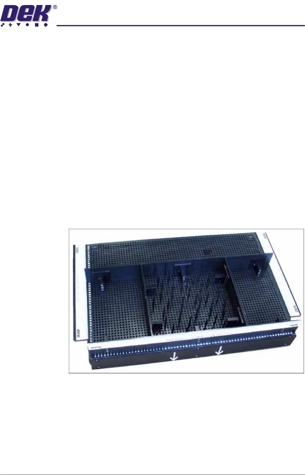
MULTIFLEX TOOLING
The MultiFlex tooling plate hardware consists of a hollow box constructed from
four adjustable side plates. The side plates are secured to the MultiFlex tooling
plate using magnets. The tooling plate is located on the tooling table by means
of dowels.
Board support is provided by double ended steel pins on a 5mm matrix. One
end is 3mm tapering down to 1mm to allow for support of densely populated
boards.
Vacuum (option) is achieved using the Venturi effect on the mains air supply.
The vacuum is variable by adjustment of the speed controller. A gauge on the
Venturi vacuum pump indicates the amount of vacuum. The speed controller,
solenoid and Venturi vacuum pump are mounted on a bracket and located at
the rear on the lower left hand side of the machine.
The solenoid valve and hence the vacuum is controlled from MultiMove card
(X12) in the machine controller enclosure.
The MultiFlex tooling plate is 14 inches x 10 inches. The tooling height is the
same as a standard magnetic tooling pin, ie 81mm.
The 3mm diameter tooling pins are placed on the 5mm pitch matrix according
to the particular board configuration, to support the board, and yet miss any
components, or features present.
Figure 19-4 MultiFlex Tooling