Printer 600 Board Support Tooling Module.pdf - 第19页
%2$5'68 33257722/,1* 02'8/( )250)/(; 722/,1* Chapter Issue 2 May 03 Technical Reference Manual 19.19 Setting W eight Assembly The setting weight as sembly is used to verify the FormFlex pi n pressure i s se…
19.18 Technical Reference Manual Chapter Issue 2 May 03
%2$5'6833257722/,1*02'8/(
)250)/(;722/,1*
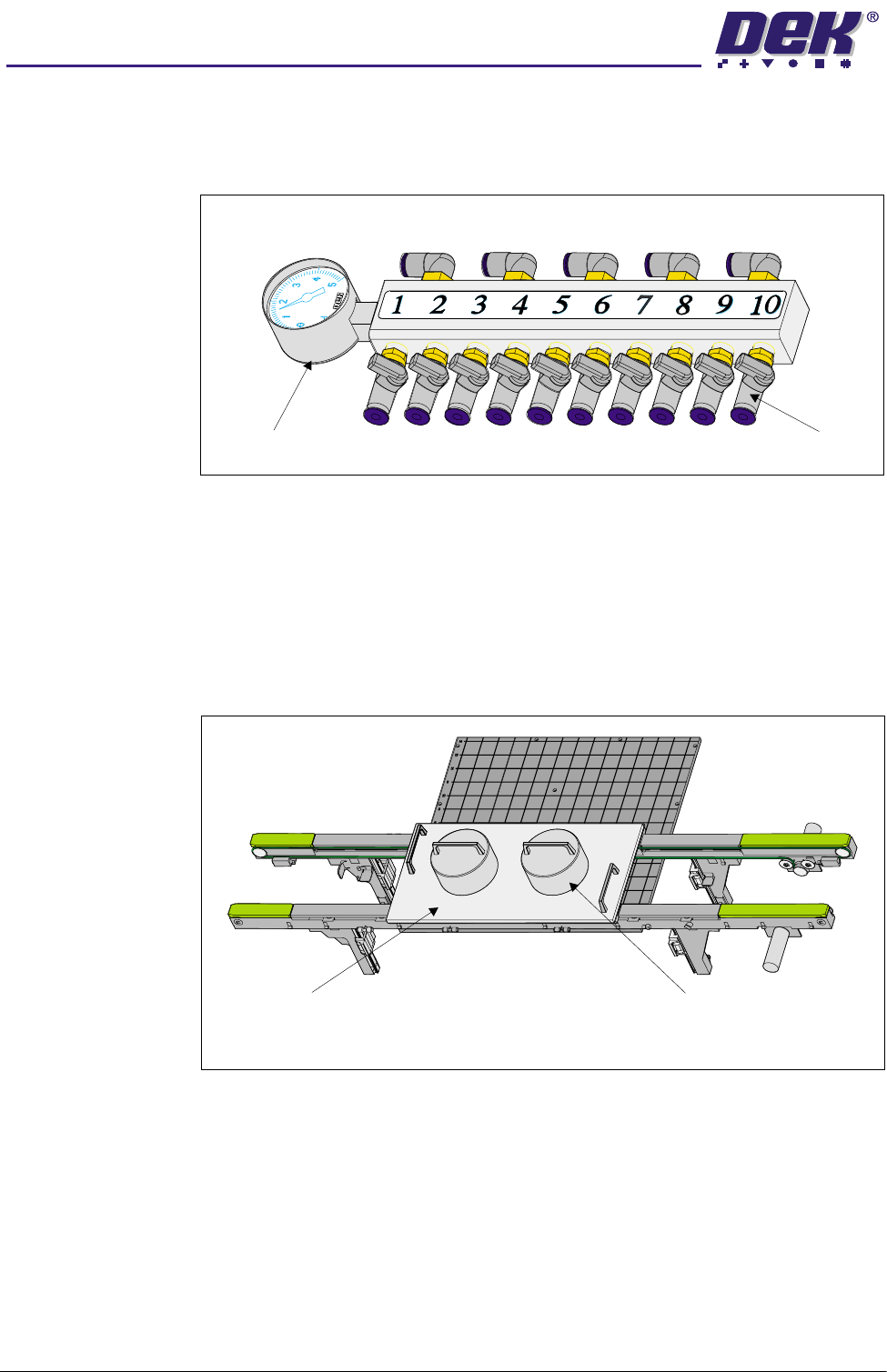
Manifold Assembly The manifold assembly contains ten ball valves allowing individual connection
of up to ten tooling modules. Fitted to the left hand end of the manifold assembly
is a -1 to +5 bar pressure/vacuum gauge, used as an aid to fault finding.
Figure 19-14 Manifold Assembly
Setup Plate and
Weights
The FormFlex setup plate and weights are utilized during tooling setup to
ensure the FormFlex pins conform to the product profile. It consists of an
aluminium base plate and 6kg weights.
The plate is positioned centrally over the tooling modules and rails, the weights
are placed on the plate centrally in the Y axis and one third of the plate length
in the X axis.
Figure 19-15 Setup Plate and Weights
Pressure Gauge
Ball Valves
Setup Plate Weight (in 2 positions)
Plan View on Rails & Manual Tooling Plate
%2$5'6833257722/,1*02'8/(
)250)/(;722/,1*
Chapter Issue 2 May 03 Technical Reference Manual 19.19
Setting Weight
Assembly
The setting weight assembly is used to verify the FormFlex pin pressure is set
to approximately 250gms on the following occasions:
• After Installation
• Validate pressure when required
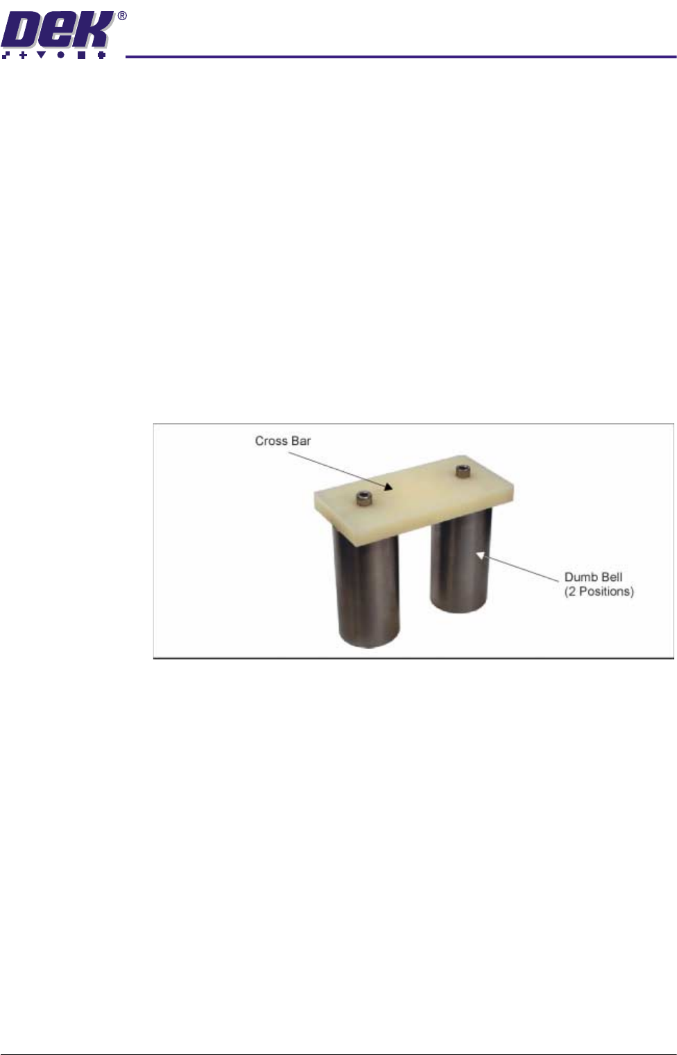
The unit is constructed from a pair of solid cylindrical metal dumb-bells secured
to a plastic cross bar by two cap headed screws. The weight of the assembly
is 1.25kg ±0.01.
The unit is placed over a tooling module, the cross bar covers an area of five/
six FormFlex pins. The system is operated, if the unit is raised off the tooling
plate by the six FormFlex pins, the combined pin pressure is greater than
1.25kg. Hence, each pin pressure is greater than 208gms.
If the unit is placed over an area of five FormFlex pins and the system is
operated and the FormFlex pins fail to raise the setting weight assembly, the
combined pin pressure is less than 1.25kg. Hence, each pin pressure is less
than 250gms.
Figure 19-16 Setting Weight Assembly
19.20 Technical Reference Manual Chapter Issue 2 May 03
%2$5'6833257722/,1*02'8/(
)250)/(;722/,1*
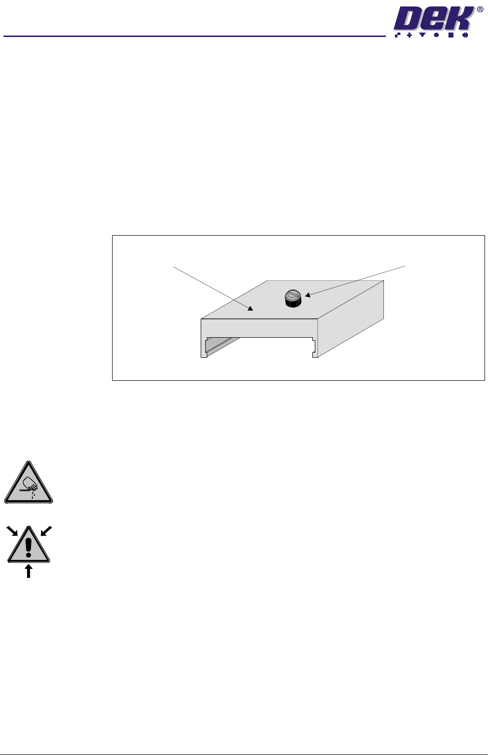
Blanking Plate Kit To improve gasketing when printing thin flexible boards, a set of blanking plates
are clamped to the top of the tooling modules to prevent FormFlex pins not
supporting the board and squeegee/ProFlow transfer head from rising.
The blanking plates are available in the following lengths:
• 100mm - Disables ten FormFlex pins
• 50mm - Disables five FormFlex pins
• 12mm - Disables one/two FormFlex pins
During product setup, the appropriate sized blanking plates are slid onto the
tooling module outside the area of the squeegees/ProFlow and clamped in
place using the M4 x 6mm slotted thumb screw.
Figure 19-17 Blanking Plate
Adjustments and Settings
FormFlex Pin Pressure
WARNING
BOARD CLAMPS. EXTREME CARE MUST BE EXERCISED WHEN WORKING IN
THE TOOLING AREA OF THE MACHINE TO AVOID INJURY. THE FOILS ON THE
FRONT AND REAR BOARD CLAMPS ARE VERY SHARP.
WARNING
COMPRESSED AIR. COMPRESSED AIR SHOULD NEVER IMPINGE UPON THE
BODY. PORTS, PIPES, ETC MUST NEVER BE BLOCKED BY HAND. BEFORE
CONNECTING ANY PNEUMATIC EQUIPMENT TO A COMPRESSED AIR SUPPLY,
ALL MOUNTINGS, FITTINGS, PIPEWORK AND ELECTRICAL CONNECTIONS
SHOULD BE REMOVED FOR SAFETY. NO PIPEWORK ALTERATIONS OR
REMOVAL OF FITTINGS SHOULD BE ATTEMPTED WITH AIR SUPPLIES
CONNECTED.
1. Gain access to manual tooling plate.
2. Connect the module under test to either manifold outlet 1 or 2.
Blanking Plate M4 x 6mm Slotted Thumbscrew