Printer 600 Board Support Tooling Module.pdf - 第9页
%2$5'68 33257722/,1* 02'8/( )250)/(; 722/,1* Chapter Issue 2 May 03 Technical Reference Manual 19.9 Element s The FormFlex T ooli ng comprises the foll owing element s: • T ooling Modules • Sequencer and Pe…
19.8 Technical Reference Manual Chapter Issue 2 May 03
%2$5'6833257722/,1*02'8/(
)250)/(;722/,1*
FORMFLEX TOOLING
Purpose FormFlex tooling is a fully automated tooling facility that conforms to any given
board profile, fully supporting the underside of a populated board and stencil.
FormFlex tooling array consists of 6 tooling modules with pin up/down control,
and each module contains 44 pins in two rows. The FormFlex array is held
magnetically to the manual tooling plate with the front unit being dowel located.
The FormFlex tooling height is 81mm standard tooling height, with a maximum
component under board clearance of 15mm.
With the board loaded and raised to print height, all the FormFlex pins are
extended using hydraulic fluid pressure until they meet the underside of the
board, stencil or component. Once all the pins are in contact, the fluid supply to
the pins is cut-off, automatically locking the pins in position. Variations in the
board layout can be accommodated as the force necessary to vary the height
of a single pin is small enough not to damage a component.
Figure 19-7 FormFlex Tooling Elements
%2$5'6833257722/,1*02'8/(
)250)/(;722/,1*
Chapter Issue 2 May 03 Technical Reference Manual 19.9
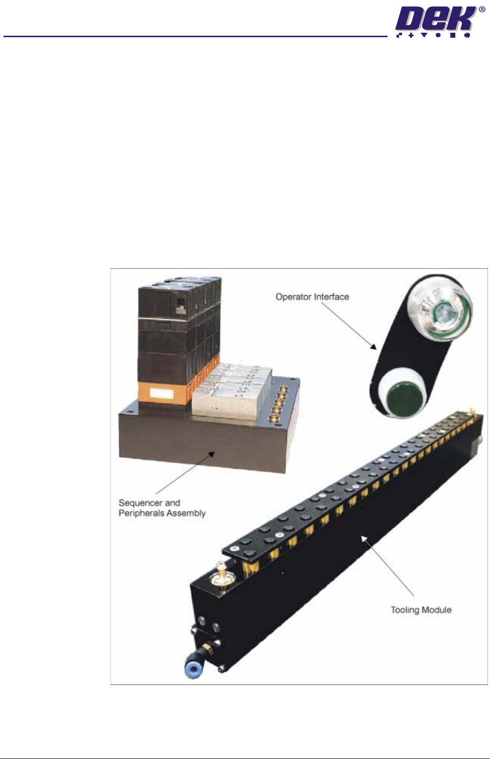
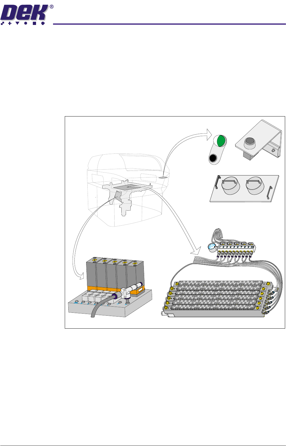
Elements The FormFlex Tooling comprises the following elements:
• Tooling Modules
• Sequencer and Peripherals Assembly
• Pneumatic Logic Components
• Operator Interface
• Manifold Assembly
• Setup Plate and Weights (2 in number)
Figure 19-8 Location of Elements
Configuration The standard Formflex tooling system configuration of six tooling modules can
be configured to handle the following board sizes:
• Minimum board size - 38mm x 50mm
• Maximum board size - 254mm x 508mm
• Board thickness - 0.4 - 5.0mm
Sequencer and Peripherals Assembly
Operator Interface
Tooling Modules
Manifold Assembly
Setting Weights & Plate
19.10 Technical Reference Manual Chapter Issue 2 May 03
%2$5'6833257722/,1*02'8/(
)250)/(;722/,1*
Operation With all the FormFlex pins in the lowered position, a board is loaded to the
machine print station. The FormFlex setup plate and weights are placed
centrally over the board and transport rails, the rising table is raised to print
height.
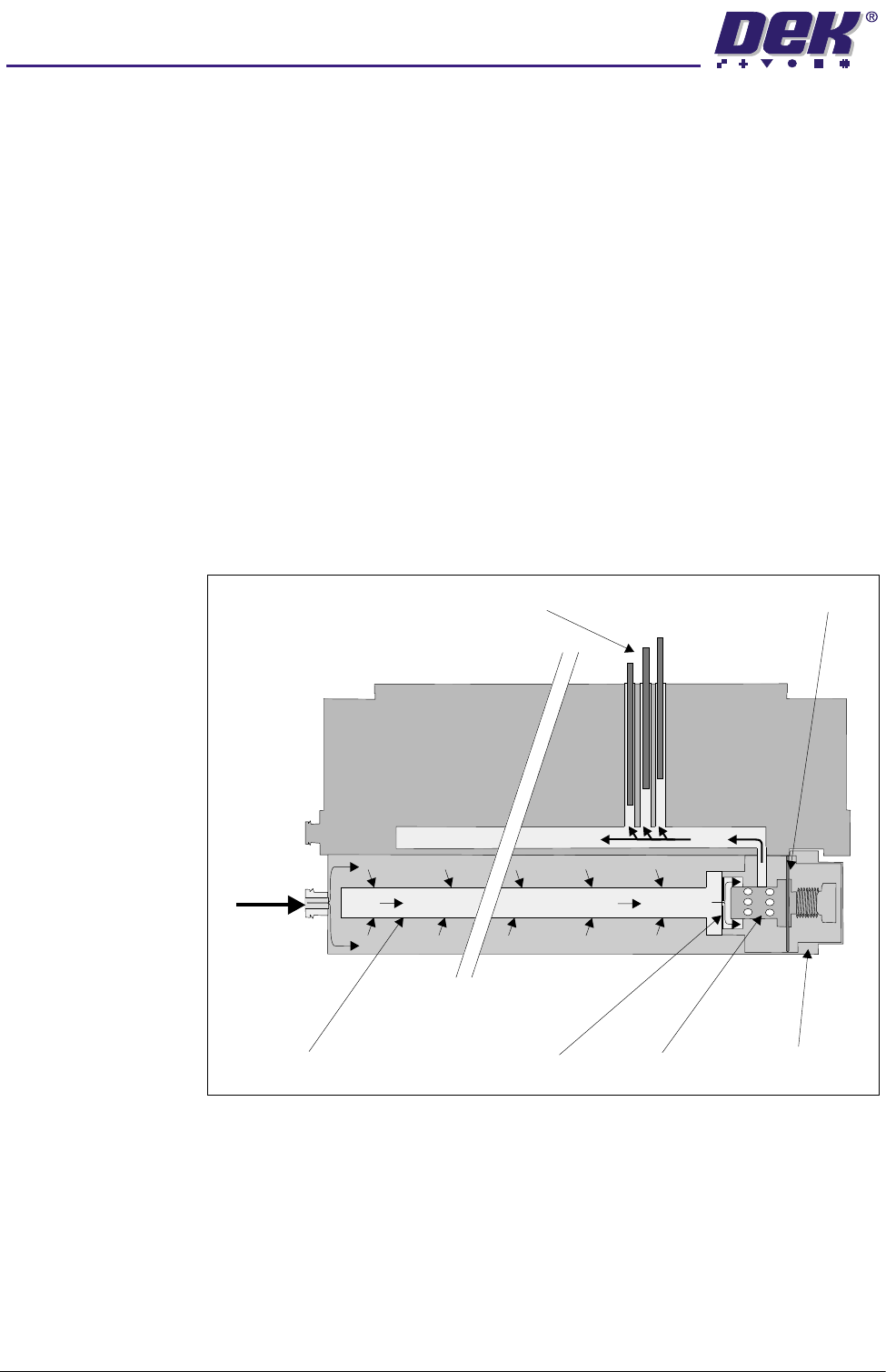
When the operator switch on the machine covers is selected, air pressure is
applied to the FormFlex tooling module via an air pilot valve fitted to the
sequencer and peripherals assembly. Pressure is applied to the outer surface
of the fluid filled butyl rubber tube. Fluid pressure begins to act on the fluid cut-
off valve.
Fluid flows through the flow restrictor on the front face of the cut-off valve.
Initially, the fluid flows through the bores in the valve stem to the channel
connecting the FormFlex pins causing the pins to rise. Hydraulic pressure
begins to act on the valve membrane causing the valve stem to move against
the valve compression spring.
Once the FormFlex pins have conformed against the stencil, board or compo-
nent, movement of the cut-off valve stem completely seals the channel connect-
ing the FormFlex pins. This prevents any additional fluid flow, thus locking the
FormFlex pins in this configuration.
Figure 19-9 Cross Sectional View of Tooling Module
Five pneumatic timers situated on the sequencer and peripherals assembly, are
used to control the sequence of raising the FormFlex pins and operating the
pneumatic indicator when all the pins have risen.
Pneumatic
Pressure
Fluid Cut-Off Valve
FormFlex Pins
Pneumatic Pressure
Butyl Rubber Tube
Fluid Pressure
Valve Stem
Valve Membrane
Flow Restrictor