Printer 600 Board Support Tooling Module.pdf - 第16页
19.16 Technical Reference Manual Chapter Issue 2 May 03 %2$5'6 833257722/,1* 02'8/( )250)/(;7 22/,1* Pneumatic Logic Component s The pneumatic logic component s consists: • OR Gate • NOT Gate • YES Gate The…
%2$5'6833257722/,1*02'8/(
)250)/(;722/,1*
Chapter Issue 2 May 03 Technical Reference Manual 19.15
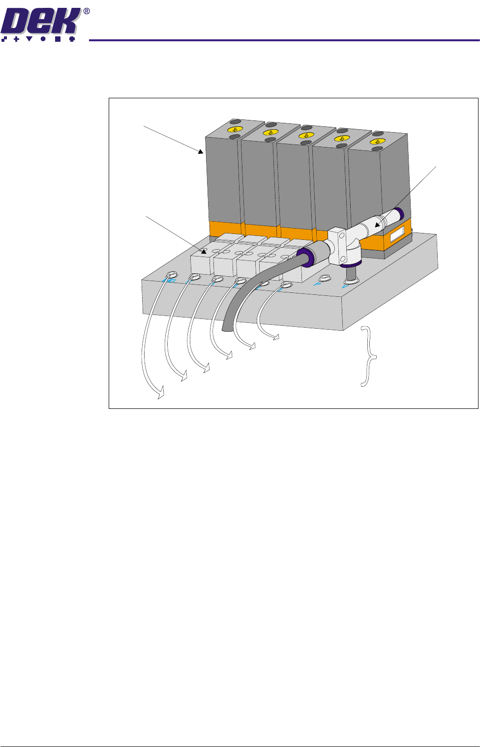
Air Pilot Valves These devices are used to connect the vacuum ejector with the tooling modules,
applying vacuum to lower the FormFlex pins.
Figure 19-11 Sequencer and Peripherals Assembly
Vacuum Ejector This device also known as a venturi vacuum pump provides vacuum to the
FormFlex tooling system to lower the FormFlex pins during product changeover.
Pneumatic Timers These devices are used to control the sequence of raising the FormFlex pins
and control the output to the pneumatic indicator during product setup. The
timers are connected in series and four of these each control a pair of tooling
modules. Each of the timers introduce a 20 second cumulative delay in raising
the tooling pins. The fifth timer controls the visual indication to the operator that
all the FormFlex pins have risen.
Pneumatic Timers
Vacuum Ejector
Air Pilot Valves
Manifold
Assembly
Supply
Tooling Modules 1 & 2
Tooling Modules 3 & 4
Tooling Modules 5 & 6
Tooling Modules 7 & 8
Tooling Modules 9 & 10
Pneumatic Indicator Supply
19.16 Technical Reference Manual Chapter Issue 2 May 03
%2$5'6833257722/,1*02'8/(
)250)/(;722/,1*
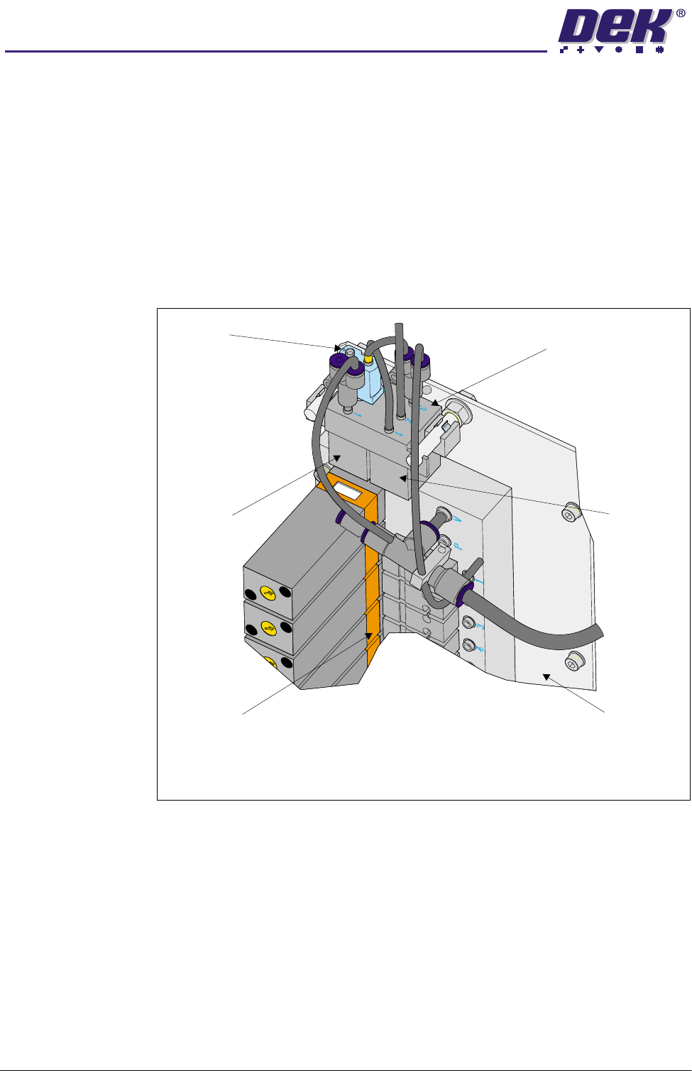
Pneumatic Logic
Components
The pneumatic logic components consists:
• OR Gate
• NOT Gate
• YES Gate
These components are fitted to a base unit located above the pneumatic
sequencer and peripherals assembly on the sequencer block and logic plate.
These components produce a pneumatic hold on circuit for the operator switch
allowing the operator to release the operator switch during raising of the
FormFlex pins.
Figure 19-12 Pneumatic Logic Components
View on Rear of Machine Above M23 ac Power Supply
Pneumatic Logic Base
OR Gate
NOT Gate
YES Gate
Sequencer Block and
Logic Plate
5 Timer Sequencer and
Peripherals Assembly
%2$5'6833257722/,1*02'8/(
)250)/(;722/,1*
Chapter Issue 2 May 03 Technical Reference Manual 19.17
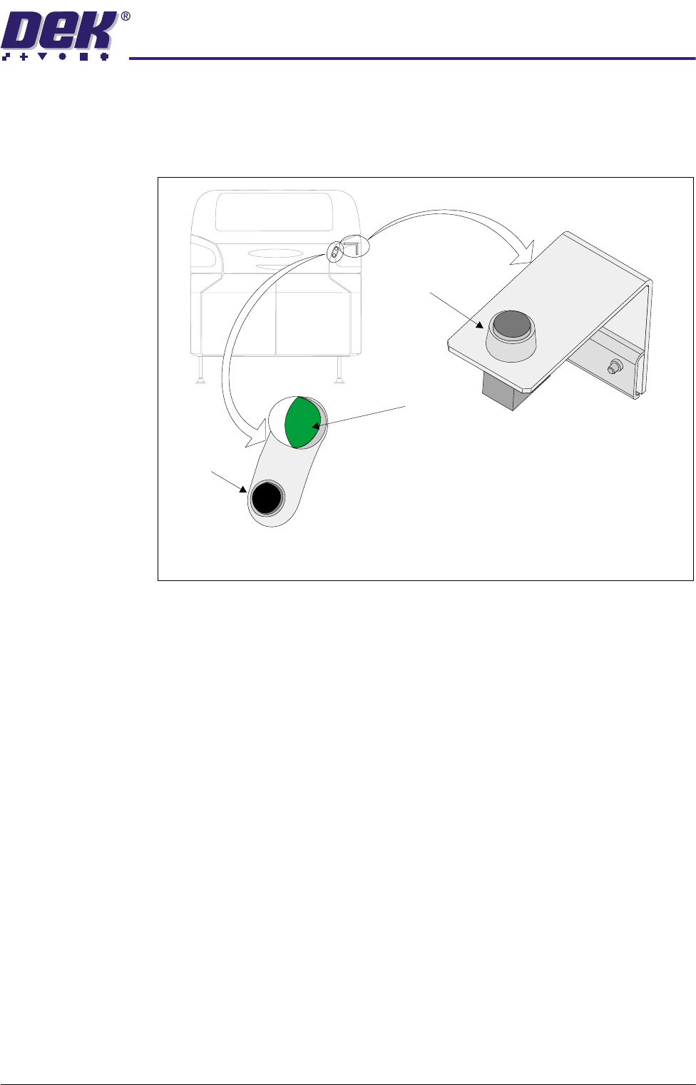
Operator Interface The operator interface comprises the following two assemblies:
• Operator Switch and Indicator Assembly
• Reset Switch Assembly
Figure 19-13 Operator Interface
Operator Switch &
Indicator Assembly
This assembly is fitted externally to the machine covers enabling immediate
access to the operator switch and a visual indication of position of the FormFlex
pins. The operator switch is a push button non latching pneumatic valve used
by the operator to raise the FormFlex pins during tooling setup. The pneumatic
indicator displays after the last pneumatic timer valve has operated, giving an
indication that all FormFlex pins have risen.
Reset Switch
Assembly
The reset switch assembly is fitted internally under the front printhead cover.
Operation of this push button non latching valve lowers the FormFlex pins thus,
resetting the FormFlex tooling for another product.
Reset Switch Assembly
(Internal)
Operator Switch & Indicator Assembly
(External)
Reset Switch
Pneumatic Indicator
Operator Switch