Printer 600 Board Support Tooling Module.pdf - 第29页
%2$5'68 33257722/,1* 02'8/( )250)/(; 722/,1* Chapter Issue 2 May 03 Technical Reference Manual 19.29 Resetting V alve S tem (Pins Down) W ARNING HARMFUL SUBST ANCES. CLEANING WIP ES AND CLEANING SOLUTIONS M…
19.28 Technical Reference Manual Chapter Issue 2 May 03
%2$5'6833257722/,1*02'8/(
)250)/(;722/,1*
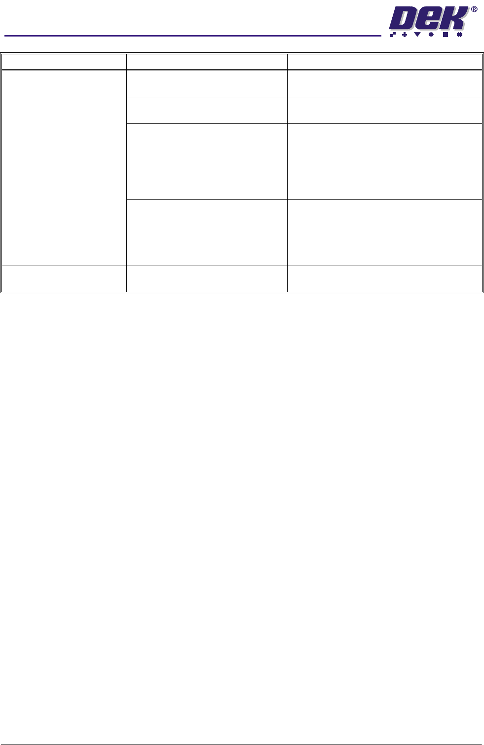
All pins not being raised in one
tooling module.
1. Ball valve on manifold assembly
incorrectly set.
1. Ensure ball valve is in the open position.
2. Air leak between sequencer, mani-
fold and tooling module.
1. Check the connections between the units,
ensuring no air leaks present.
3. Supply pipe to tooling module incor-
rectly connected.
1. Check for correct pipe connections at the
sequencer, manifold and tooling module
2. Confirm pipe connections by disconnecting
the supply pipe to the tooling module at the
module. Press the operator switch, air should
escape from the pipe at the relevant point in the
setup sequence.
4. Sticky FormFlex pins. 1. If no fault found, carry out Resetting the Valve
Stem (Pins Down) procedure later in this section.
On completion, recycle the system until all pins
raise and lower smoothly.
2. If pins fail to rise, contact DEK Customer
Support.
Oil found leaking from tooling
module.
1. Contact DEK Customer Support.
Symptom Possible Causes Possible Solutions
%2$5'6833257722/,1*02'8/(
)250)/(;722/,1*
Chapter Issue 2 May 03 Technical Reference Manual 19.29
Resetting Valve Stem (Pins Down)
WARNING
HARMFUL SUBSTANCES. CLEANING WIPES AND CLEANING SOLUTIONS MAY
CONTAIN SUBSTANCES HAZARDOUS TO HEALTH. OBSERVE ALL
MANUFACTURERS’ HEALTH AND SAFETY GUIDELINES. ALWAYS WEAR
APPROVED PROTECTIVE CLOTHING WHEN CLEANING THE MACHINE.
WARNING
BOARD CLAMPS. EXTREME CARE MUST BE EXERCISED WHEN WORKING IN
THE TOOLING AREA OF THE MACHINE TO AVOID INJURY. THE FOILS ON THE
FRONT AND REAR BOARD CLAMPS ARE VERY SHARP.
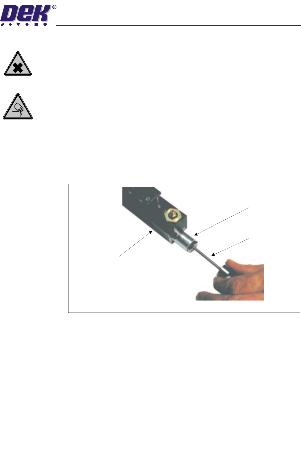
1. Gain access to the manual tooling plate.
2. Connect the tooling module to the No 1 output of the manifold assembly.
3. Press the operator switch on the front of the machine covers.
4. Insert the override pin into the central bore of the relevant tooling module
cut-off valve.
5. Apply pressure to release the cut-off valve stem. The FormFlex pins should
now begin to rise.
6. Remove the override pin from the cut-off valve.
7. Reset the FormFlex tooling.
8. Cycle the FormFlex tooling until all the pins rise during setup.
Tooling Module
Cut-Off Valve
End View of Tooling Module
Override Pin
19.30 Technical Reference Manual Chapter Issue 2 May 03
%2$5'6833257722/,1*02'8/(
)250)/(;722/,1*
Resetting the Valve Stem (Pins Up)
WARNING
HARMFUL SUBSTANCES. CLEANING WIPES AND CLEANING SOLUTIONS MAY
CONTAIN SUBSTANCES HAZARDOUS TO HEALTH. OBSERVE ALL
MANUFACTURERS’ HEALTH AND SAFETY GUIDELINES. ALWAYS WEAR
APPROVED PROTECTIVE CLOTHING WHEN CLEANING THE MACHINE.
WARNING
BOARD CLAMPS. EXTREME CARE MUST BE EXERCISED WHEN WORKING IN
THE TOOLING AREA OF THE MACHINE TO AVOID INJURY. THE FOILS ON THE
FRONT AND REAR BOARD CLAMPS ARE VERY SHARP.
Carry out this procedure if during resetting FormFlex pins remain up whilst
vacuum is applied to the tooling module.
1. Gain access to the manual tooling plate.
2. Ensure the FormFlex tooling has been reset.
3. Disconnect the tooling module from the manifold assembly.
4. Insert the override pin into the central bore of the relevant tooling module
cut-off valve.
5. Apply pressure to release the cut-off valve stem.
6. Remove the override pin from the cut-off valve.
7. Connect the tooling module to the No 1 output of the manifold assembly.
8. Cycle the FormFlex tooling until all the pins rise and fall smoothly.
Lubrication of Pin
Seals
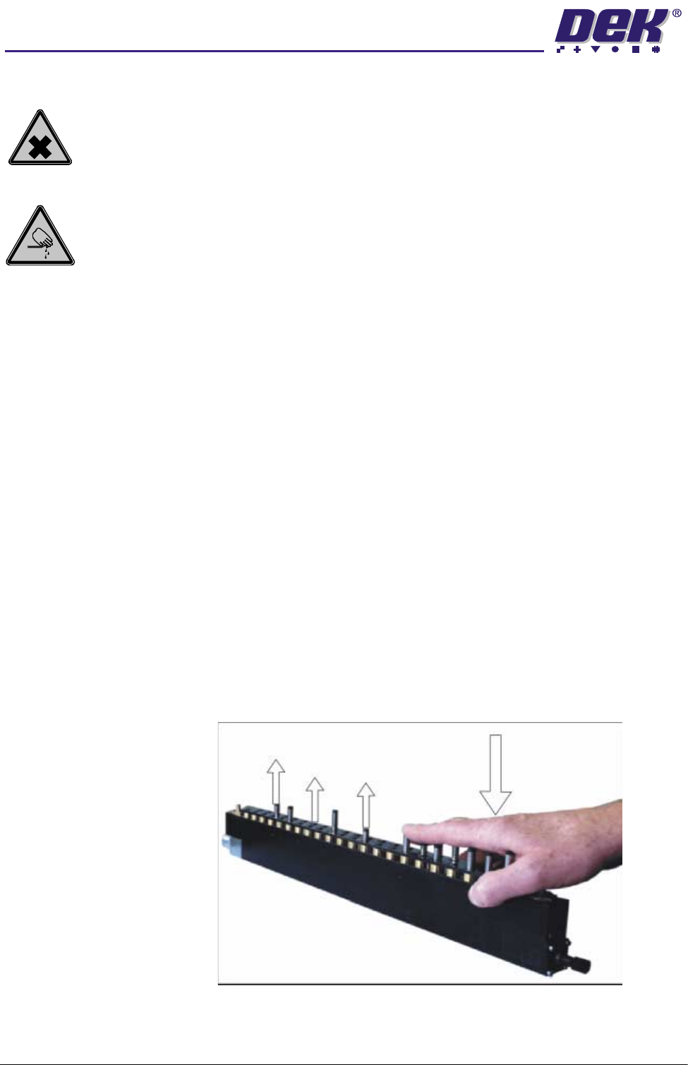
Carry out this procedure if during initial setup after a period of inactivity some
FormFlex pins do not raise in one or more tooling modules.
1. Gain access to the manual tooling plate.
2. Press the green operator switch on the machine front cover.
3. Wait until the system has fully completed its setup cycle. Manually depress
the raised FormFlex pins on affected tooling modules, forcing the lowered
pins to raise.
4. Repeat Steps 2 and 3 until all FormFlex pins raise during tooling setup.
5. If, one or more pins remain lowered after this procedure, replace the tooling