forte_en.pdf - 第14页
Page 14 command line providin g for unatt ended program mer operation in rou tine programming, environment personalization in cl. keyboard shortcut s, auto matic generation of serial numbers, etc. UP has been developed f…

Page 13
High Speed
Compared to the PRESTO programmer, FORTE features an
embedded processor making it possible to perform
complex operations with the device being programmed as
well as offering a significantly faster output interface. Due
to this, devices may be programmed up to the limits of
their theoretical performance.
USB Connection
FORTE is controlled and powered through a USB port. It
communicates in the High-Speed mode (480Mbps) /
connected to a USB 2.0 port and in the Full-Speed mode /
connected to a USB 1.1 port. This means that connecting
the programmer is fast and easy, requiring only a single
cable.
Programming of Placed Devices
ISP (In-System Programming) or the special ICSP (In-
Circuit Serial Programming) for the PIC microcontrollers is
currently replacing the traditional method in which
devices were first programmed and only then placed on a
PCB (printed circuit board). Thanks to ISP even SMD
devices with an extremely narrowly spaced pins can
easily be programmed and their firmware upgraded in
already assembled and finished devices.
Programming of Autonomous Devices
Those who still need to program autonomous devices, i.e.
devices not yet placed on a PCB can use the ISP2ZIF
adapter featuring a ZIF (zero insertion force) socket.
Programming Interface
The FORTE programmer features 8 independent I/O pins
with individually configurable pull-up/down resistors.
Devices to be programmed are connected through a
16-pin ISP connector, which is backward compatible with
the 8-pin ICSP connector for PIC microcontrollers. VPP can
be set to any value between 6.5 V and 17 V.
Connection to a remote application through a 16-wire
ribbon cable has been improved by interleaving its
individual signals with ground.
Power Supply From Application
The VDD output can serve as an input using the power
from the application for feeding the output buffers, or it
can become an output and as such to provide voltage for
the application.
FORTE can power applications with a voltage from 1.8V
to 5.5V. A controlled discharge resistor is incorporated
for faster transitions between different programming
phases when capacitors in the application need to be
discharged all the way down to 0V.
FORTE includes a built-in “voltmeter” at pins P and VDD.
Overcurrent Protection
FORTE includes a fast-responding hardware overcurrent
protection at pins P and VDD, which is independent of the
state of the controlling PC.
User Interface
The programmer status is clearly indicated by two LEDs.
ON-LINE (green LED) informs of connecting to USB while
ACTIVE (two-state yellow/red LED) signals an activity or a
faulty state (error) of the programming interface.
The GO button significantly increases the operator’s
comfort in repeated programming. It starts programming
or other user-defined commands
Software
The UP program is a basic software tool for working with
FORTE, also compatible with the PRESTO programmer.
Apart from standard commands, UP provides numerous
above-standard functions, which broaden the
programmer’s applications and simplify its operation.
These include the possibility to define projects, existence
of adjustable parameters when running from the

Page 14
command line providing for unattended programmer
operation in routine programming, environment
personalization incl. keyboard shortcuts, automatic
generation of serial numbers, etc.
UP has been developed for Windows XP or later.
Modified drivers developed by FTDI are used for
communication through USB.
Devices with the JTAG interface, for which an SVF or an
XSVF file can be created, can be programmed by means
of the JTAG SVF Player software.
The voltage at the VDD pin is permanently displayed in
UP for greater comfort and for monitoring of the
operation. The reset signal is conveniently controlled by a
single button.
2.5
Controls and
Connectors
Fig.2: The FORTE programmer
FORTE features two LEDs, a button, a connector for
linking to USB and a programming connector.
2.5.1 Programming
Connector
The programming connector is a 16 way double row plug
with pin No. 3 (in standard numbering) missing. Spacing
between pins is 2.54mm.
Fig.3: Programming connector
Pin
Type
Description
P
I/O, VPP
signal input/output or VPP output
VDD
PWR
power input/output
GND
PWR
signal grounding
D, C, I, L, T, S, R
I/O
signal input/output
Table1: programming connector
Page 15
2.5.2 GO Button
This button simplifies work with the application being
programmed. It triggers device programming or another
pre-programmed function. For further information on
settings see
Setting the GO Button.
2.5.3 LED Indicators
ACTIVE
This two-state LED informs you of the equipment status.
The yellow color means that there is ongoing
communication between the programmer and a device.
A red color signals an error state.
ON-LINE
The green LED informs you that FORTE is connected to a
computer and that the computer and the programmer
“understand each other”, i.e. drivers are installed and
work correctly.
2.5.4 USB Connector
A standard USB (type B) connector is provided for
connecting to a computer. The programmer uses the
USBHigh-Speed (480 Mbps) interface for communication.
2.6
Connecting to
Application
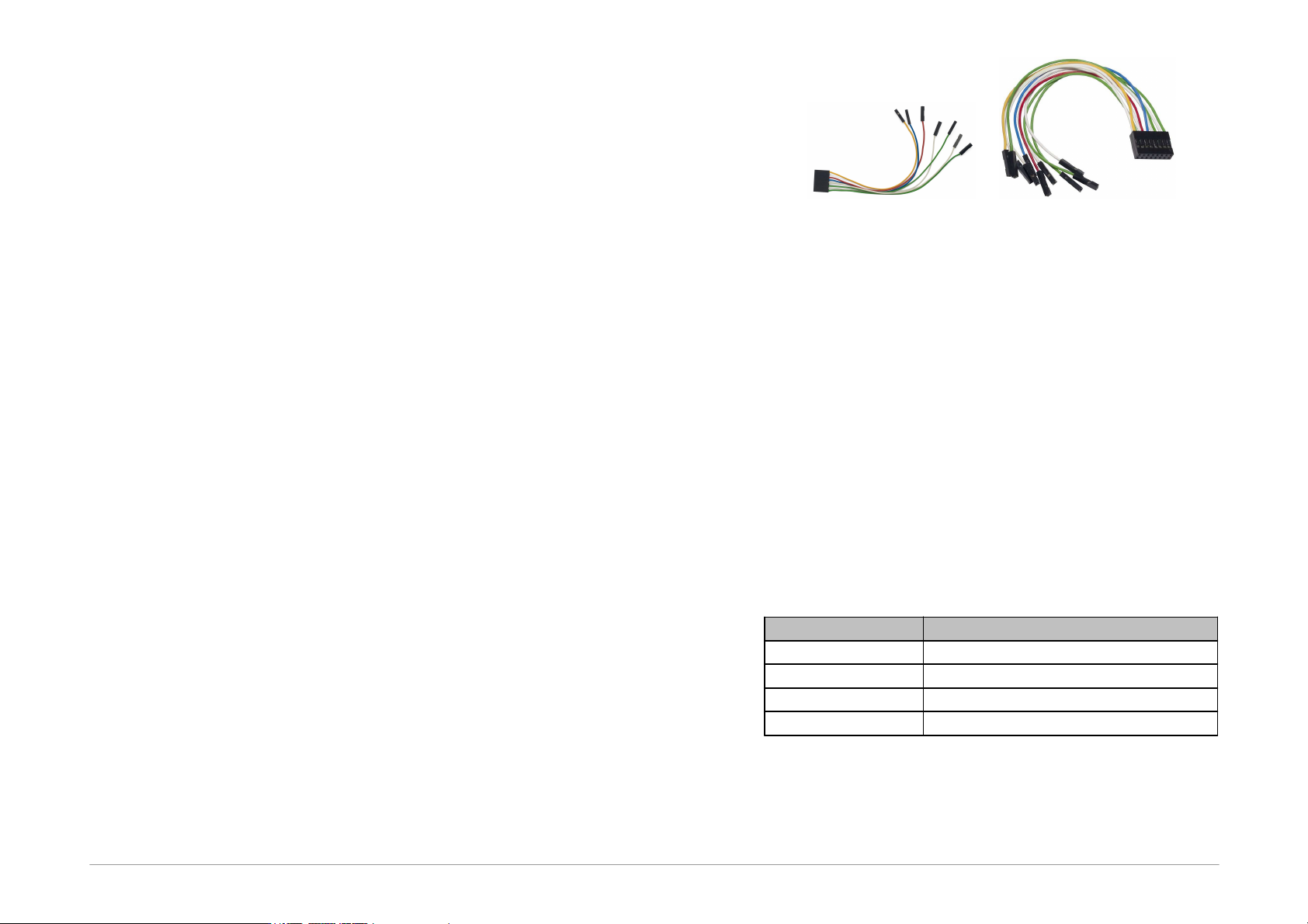
The programmer should be connected to an application to
be programmed with an ICSPCAB8 or ICSBCAB16 cable.
The cables are designed for 2.54 mm spacing.
Fig.4: ICSPCAB8
Fig.5: ICSPCAB16
The connectors are specified in the next chapter.
2.6.1 Custom-made
Connecting Cable
Should an application to be programmed have a non-
compatible type of connector for linking to the
programmer, the customer can make his/her own
programming cable. Its length should not exceed 15cm.
This is where interleaving of individual signals with GND
in a 16-wire ribbon cable can be used conveniently. In
order to utilize this ground-interleaving, all GND signals
must be actively connected on the application's side.
The following table lists markings of connectors by FCI
Electronics suitable for making a custom cable. Ofcourse,
it is possible to use any similar ones:
FCI marking
Description
65039-036LF
housing, 1 pin
65039-029LF
housing, 1 x 8 pins
65043-029LF
housing, 2 x 8 pins
47217-000LF
pin
Table2: ICSP cable - material list
A cable with a cross-section between 0.1 and 0.3 mm2
may be used for making the custom connecting cable.