forte_en.pdf - 第23页
Page 23 AT89C51CC01UA Fig.17: Mikrokontrolér AT8 9C51CC01UA 1) The ALE pin do not h ave t o be connect ed, wh en it is unconnec ted on the prog rammed device or when it is in log.1. Cypress PS oC Fig.18: Cypress PsoC m…
Page 22
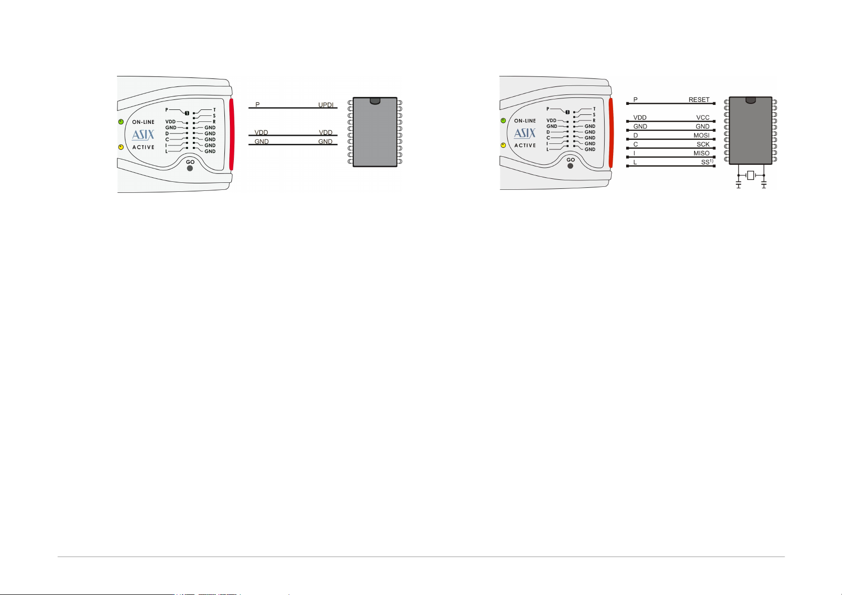
AVR with UPDI Interface
Fig.15: AVR microcontroller, UPDI interface
1) Some of the devices with separated UPDI and RESET
pins have to be also connected this way. The
connection for the selected device can be found in
the "Device/Device info" menu of the UP software.
2) On UPDI pin a 12V pulse is used to enter the
programming mode of ATtiny UPDI.
3) When the programmed device quits the
programming mode or the UPDI interface is disabled
during programming, a power-on reset of the
programmed device has to be done.
4) For AVR with UPDI data files with memories mapped
from zero are expected and their fuses save to a
project file same as for older AVRs, because Atmel
Studio creates the data files this way.
Atmel 8051
Fig.16: Atmel 8051 microcontroller
1) The SS pin must be connected only for AT89LP2052 /
4052 / 213 / 214 / 216 / 428 / 828 / 6440 / 51RD2 /
51ED2 / 51ID2 / 51RB2 / 51RC2 / 51IC2.
2) AT89LP213, AT89LP214 and AT89LP216 have the
inverse reset logic. Thus an appropriate resistor must
be pulled-up to VCC.
3) FORTE can not program devices containing the letter
“C” in their name, however, it supports devices with
“S” in their name, of which some are compatible with
the “C” types. For example, AT89C2051 is not
supported, but AT89S2051 is.
4) The software assumes that while programming
AT89LP52, the device’s POL pin is in logical1. If POL
is in logical0, the Inverse RESET option should be
activated in the program. For AT89LP51RD2,
AT89LP51ED2, AT89LP51ID2, AT89LP51RB2,
AT89LP51RC2 and AT89LP51IC2 the software
assumes the POL pin in logical0.
Page 23
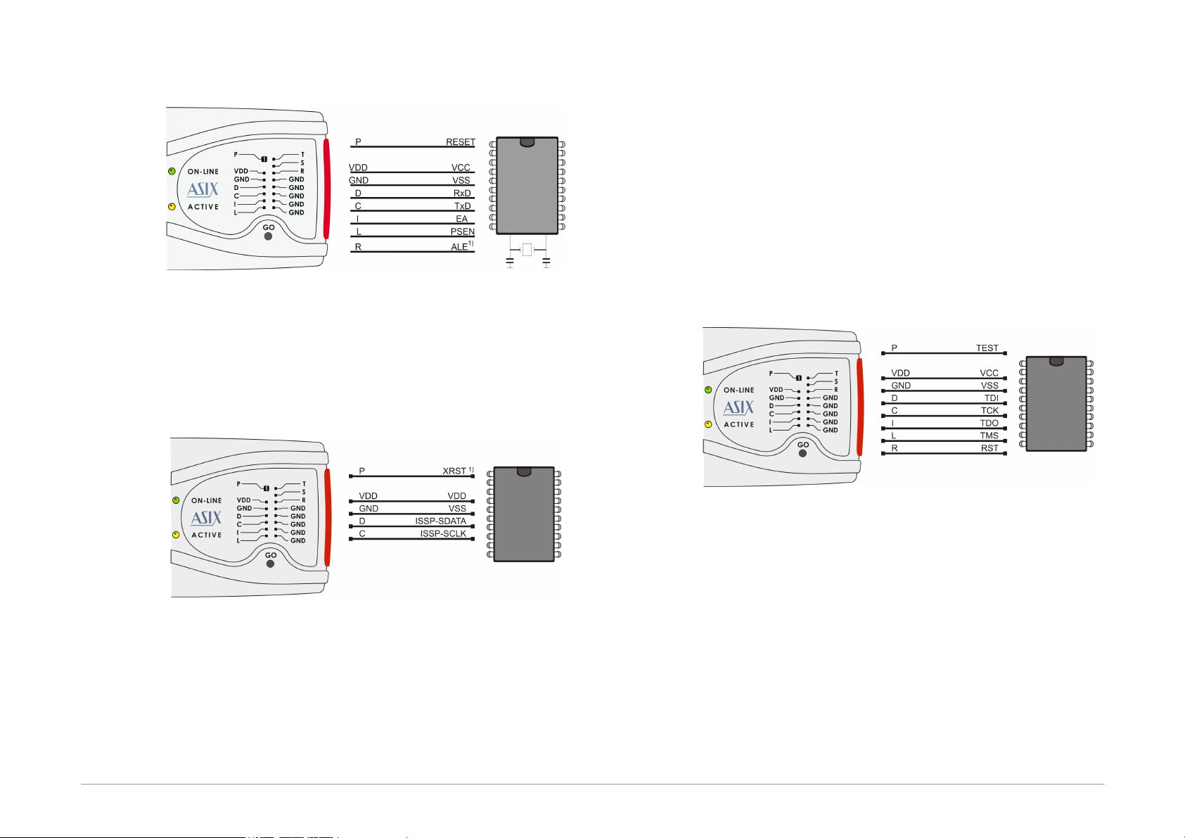
AT89C51CC01UA
Fig.17: Mikrokontrolér AT89C51CC01UA
1) The ALE pin do not have to be connected, when it is
unconnected on the programmed device or when it is
in log.1.
Cypress PSoC
Fig.18: Cypress PsoC microcontroller
1) The way of entering in the programming mode
should be set in the FORTE programmer settings
window. Devices without an XRST pin can only use
initialization through the power-on reset (by power
supply). Devices with an XRST pin may use both
methods, but the method using the reset signal for
initialization is better as it can be used in
combination with an external power supply.
2) Algorithm programming in the FORTE
programmer settings window should be set in
accordance with the power supply cable used.
MSP430 / CC430 with TEST Pin,
JTAG Interface
Fig.19: MSP430 / CC430 microcontroller, TEST pin, JTAG
interface
1) If the oscillator calibration values are saved in the
information memory and this memory is not going to
be re-programmed (erased) during programming, the
device should be programmed with the Cal Int. RC
(=calibrated internal RC oscillator) option selected in
the FORTE programmer settings window. In the
other cases Not Cal Int. RC (=not calibrated internal
RC oscillator) should be selected.
Page 24
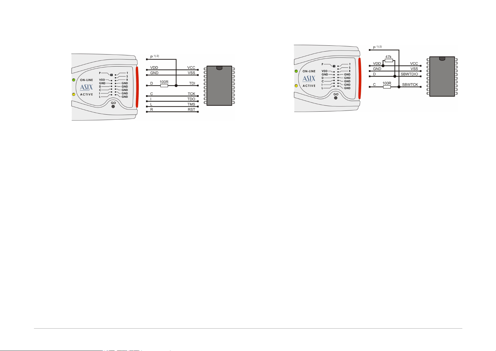
MSP430 / CC430 without TEST
Pin, JTAG Interface
Fig.20: MSP430 / CC430 microcontroller, no TEST pin, JTAG
interface
1) Pin P feeds the device with 6.5V during the fuse
programming. If the fuse is not to be programmed,
this pin does not have to be connected.
2) The MSP430F5xxx and CC430 devices lock in a
different way, i.e. pin P stays disconnected. Even the
100 R resistor can be left out in such a case.
3) If the oscillator calibration values are saved in the
information memory and this memory is not going to
be re-programmed (erased) during the programming
process, the device should be programmed with the
Cal Int. RC (=calibrated internal RC oscillator)
option selected in the FORTE programmer
settings window. In other cases Not Cal Int. RC
(=not calibrated internal RC oscillator) should be
selected.
MSP430 / CC430, SBW Interface
Fig.21: MSP430 / CC430 microcontroller, SBW interface
1) Pin P feeds the device with 6.5 V during the fuse
programming. If the fuse is not to be programmed,
this ping does not have to be connected.
2) The MSP430F5xxx and CC430 devices lock in a
different way, i.e. pin P stays disconnected. Even the
100 R resistor can be left out in such a case.
3) If the oscillator calibration values are saved in the
information memory and this memory is not going to
be re-programmed (erased) during the programming
process, the device should be programmed with the
Cal Int. RC (=calibrated internal RC oscillator)
option selected in the FORTE programmer
settings window. In the other cases Not Cal Int. RC
(=not calibrated internal RC oscillator) should be
selected. There is no need to select the oscillator for
the MSP430F5xxx and CC430 devices.
4) Speed in the FORTE programmer settings window
should be slow down if any external capacitor is
connected to the device's reset pin.
5) The FORTE programmer also erases the Segment A of
the information memory with the EraseSegmentA
option selected.