forte_en.pdf - 第16页
Page 16 2.6.2 Programming in ZIF Socket If p rogramming of aut onomous device is required, i.e. those t hat a re only later c onnected to an a pplication, it is possible b y m eans o f ou r o ptional ISP2ZIF accessory. F…
Page 15
2.5.2 GO Button
This button simplifies work with the application being
programmed. It triggers device programming or another
pre-programmed function. For further information on
settings see
Setting the GO Button.
2.5.3 LED Indicators
ACTIVE
This two-state LED informs you of the equipment status.
The yellow color means that there is ongoing
communication between the programmer and a device.
A red color signals an error state.
ON-LINE
The green LED informs you that FORTE is connected to a
computer and that the computer and the programmer
“understand each other”, i.e. drivers are installed and
work correctly.
2.5.4 USB Connector
A standard USB (type B) connector is provided for
connecting to a computer. The programmer uses the
USBHigh-Speed (480 Mbps) interface for communication.
2.6
Connecting to
Application
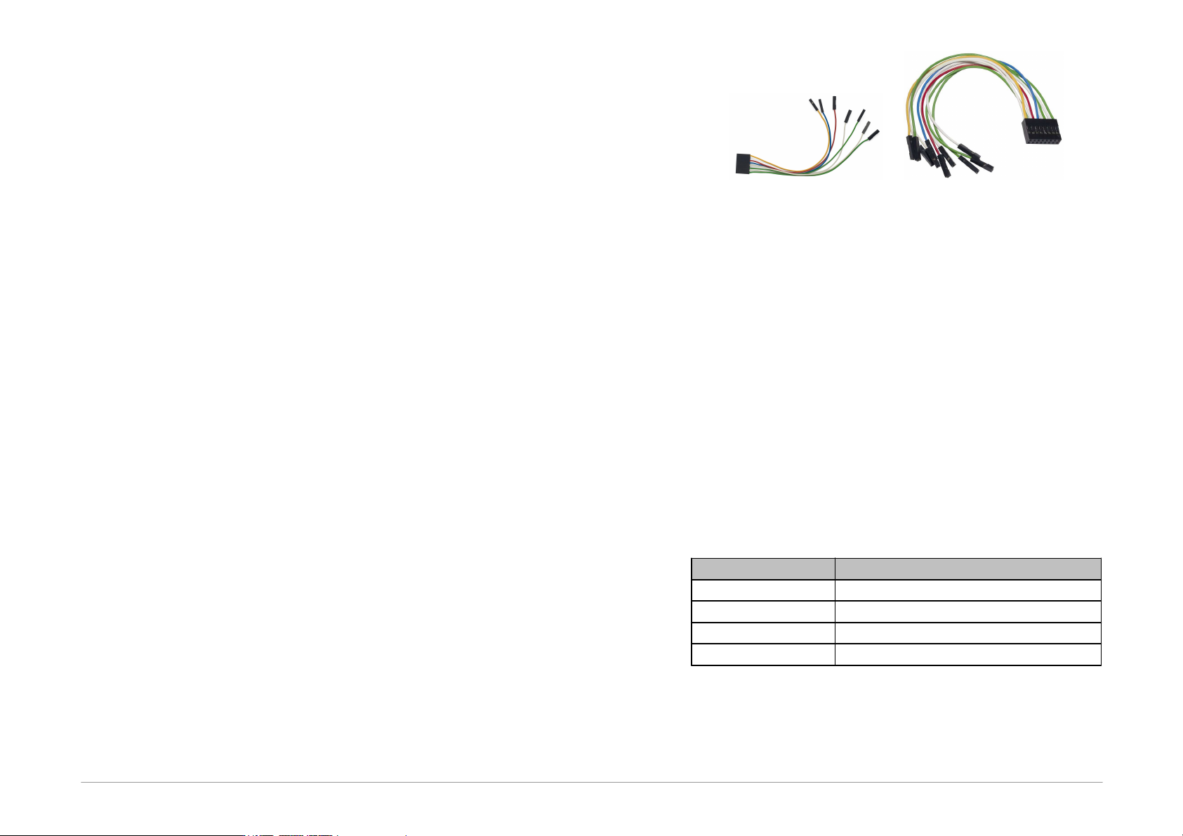
The programmer should be connected to an application to
be programmed with an ICSPCAB8 or ICSBCAB16 cable.
The cables are designed for 2.54 mm spacing.
Fig.4: ICSPCAB8
Fig.5: ICSPCAB16
The connectors are specified in the next chapter.
2.6.1 Custom-made
Connecting Cable
Should an application to be programmed have a non-
compatible type of connector for linking to the
programmer, the customer can make his/her own
programming cable. Its length should not exceed 15cm.
This is where interleaving of individual signals with GND
in a 16-wire ribbon cable can be used conveniently. In
order to utilize this ground-interleaving, all GND signals
must be actively connected on the application's side.
The following table lists markings of connectors by FCI
Electronics suitable for making a custom cable. Ofcourse,
it is possible to use any similar ones:
FCI marking
Description
65039-036LF
housing, 1 pin
65039-029LF
housing, 1 x 8 pins
65043-029LF
housing, 2 x 8 pins
47217-000LF
pin
Table2: ICSP cable - material list
A cable with a cross-section between 0.1 and 0.3 mm2
may be used for making the custom connecting cable.
Page 16
2.6.2 Programming in ZIF
Socket
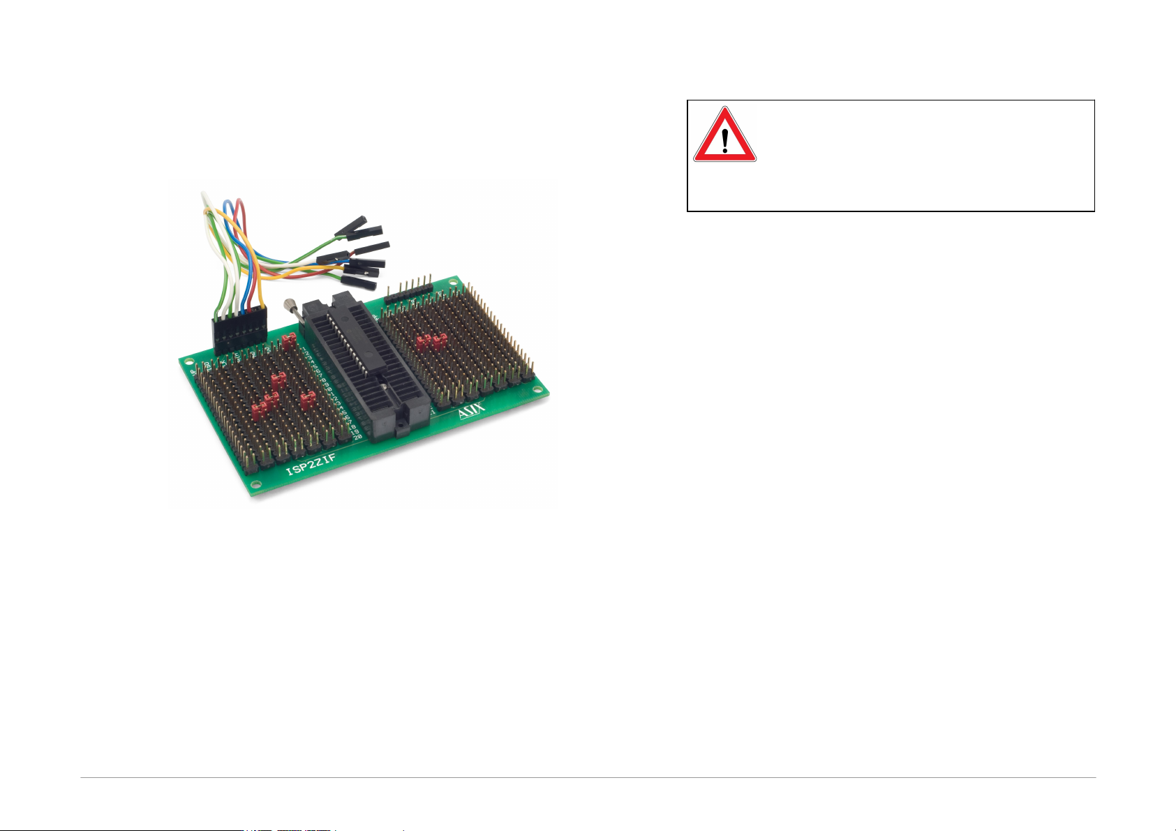
If programming of autonomous device is required, i.e.
those that are only later connected to an application, it is
possible by means of our optional ISP2ZIF accessory.
Fig.6: ISP2ZIF
ISP2ZIF consists of a zero insertion force (=ZIF) socket
and an ICSP connector for connecting to the programmer,
which can also provide voltage for feeding the program
circuitry.
2.6.3 Connecting
Procedure
The correct procedure for connecting the programmer:
first connect FORTE to the target application, then
connect FORTE to the USB and finally turn on the
application’s power supply.
Please make sure that the GND of the application, the
programmer and the USB are interconnected before
signals and the power are applied.
Important warning
If an application is powered by a switched
power source or is not grounded, a significant
voltage difference may appear between the
programmer’s ground and the application’s
ground. This could damage the programmer.
The simplest way of connecting the GND prior to the
other signals is to ground the application before
connecting it to the programmer. This can, for example,
be achieved by making the GND pin of the application’s
ICSP connector longer than the other pins. It will make
sure that both grounds are interconnected first.
Page 17
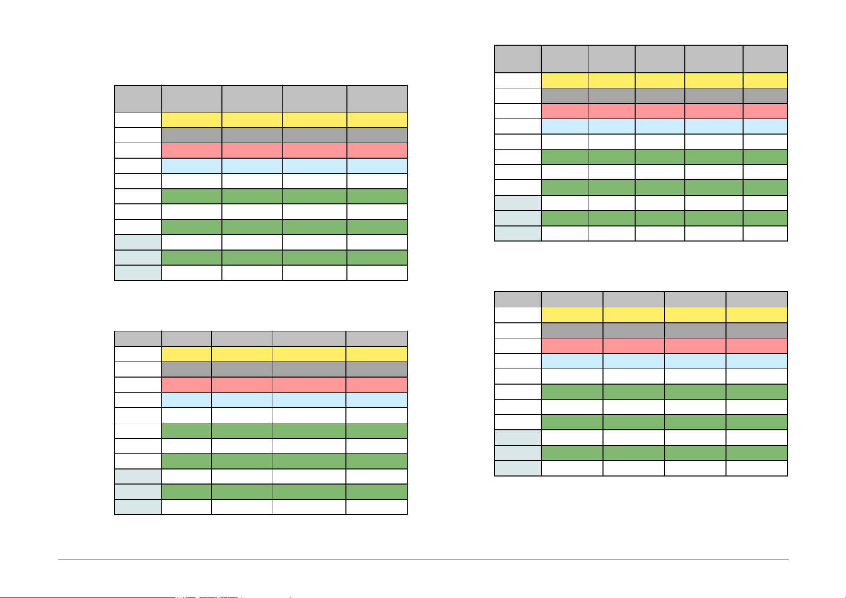
Table of Connections
Pin
AVR
AVR TPI
ATxmega
PDI
8051
P
RESET
RESET
RESET
-
VDD
VCC
VCC
VCC
VCC
GND
GND
GND
GND
GND
D
MOSI
TPIDATA
PDI_DATA
MOSI
C
SCK
TPICLK
PDI_CLK
SCK
I
MISO
MISO
L
SS
T
S
R
Table3: Connection list No.1
Pin
PIC
MSP430
MSP430 SBW
TI CCxxxx
P
MCLR
TEST/VPP
VPP
RESET
-
VDD
VDD
VCC
VCC
VDD
GND
VSS
VSS
VSS
GND
D
PGD
TDI
SBWTDIO
Debug_data
C
PGC
TCK
SBWTCK
Debug_clock
I
TDO
L
LVP
TMS
T
S
R
RESET
Table4: Connection list No.2
Pin
I
2
C
SPI
QUAD
SPI
1
Microwire
UNI/O
P
- CS
- CS
CS
-
VDD
VDD
VDD
VDD
VDD
VCC
GND
GND
GND
GND
GND
VSS
D
SDA
SI
SIO0
DI
SCIO
C
SCL
SCK
SCK
CLK
I
SO
SIO1
DO
L
SIO2
ORG/(PRE)
T
S
SIO3
R
Table5: Connection list No.3
Pin
PSoC
1-Wire
ARM SWD
LPC UART
P
XRST
IO
2
NRST
RESET
-
VDD
VDD
VDD
VDD
VDD
GND
VSS
GND
GND
VSS
D
ISSP-DATA
SWDIO
RXD
C
ISSP-SCLK
SWCLK
TXD
I
ISP
L
T
S
R
Table6: Connection list No.4