forte_en.pdf - 第18页
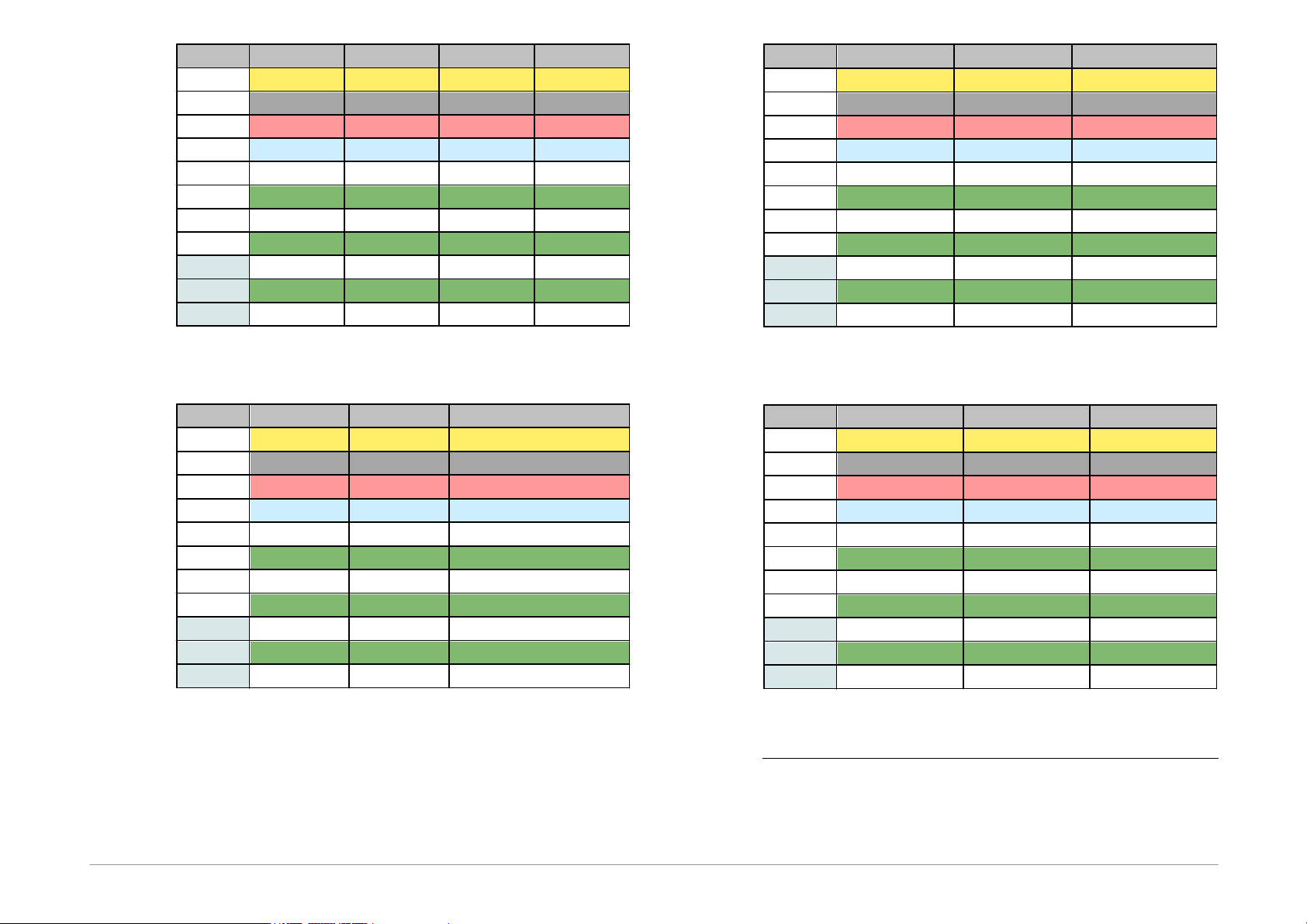
Page 18 P i n J T A G H C S 0 8 H C S x x x C 2 P U S R R E S E T - V D D V D D V D D V D D V D D G N D G N D V S S V S S G N D D T D I B K G D D a t a C 2 D C T C K C l o c k C 2 C K I T D O L T M S T S R Table7: Con n…
Page 17
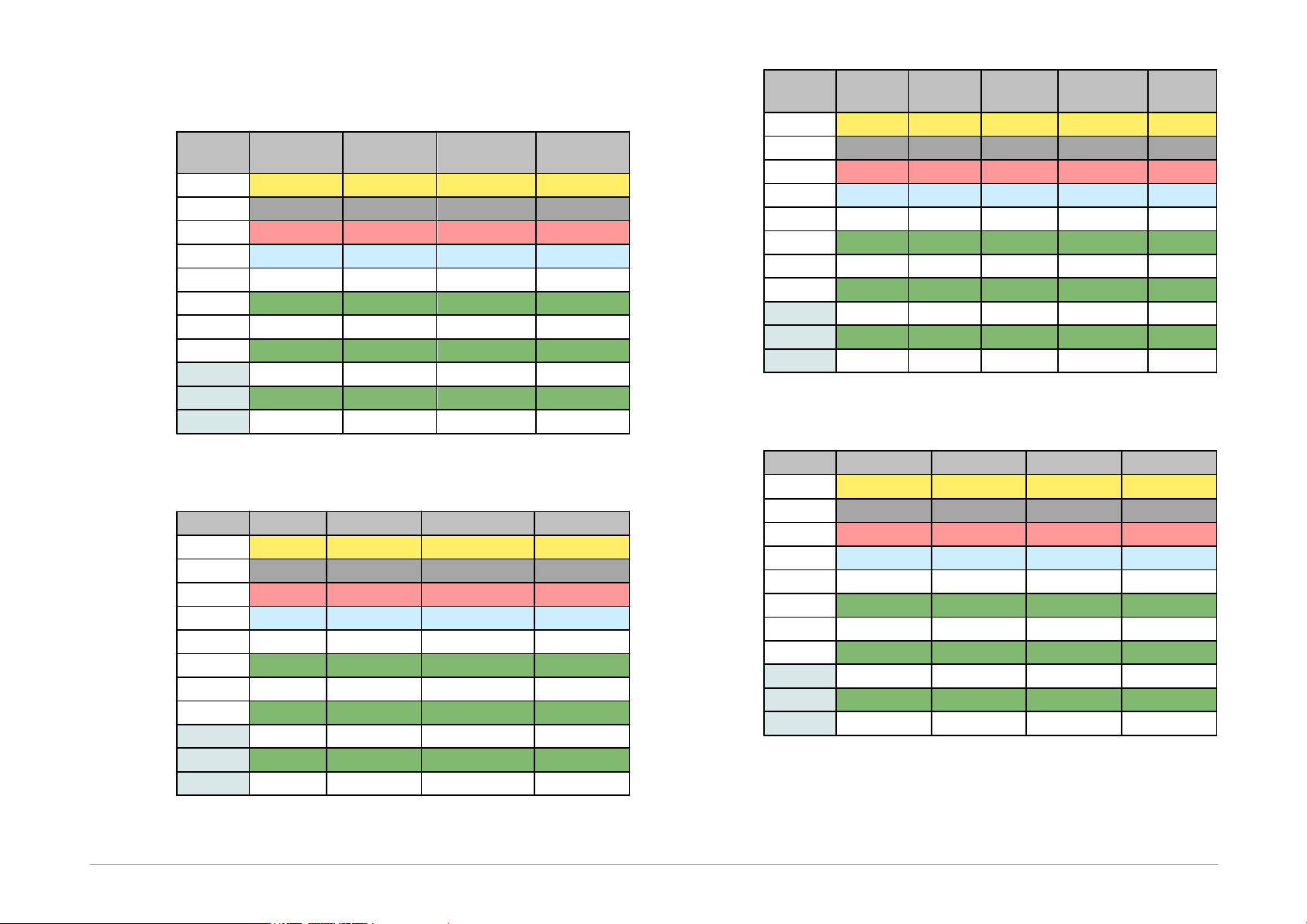
Table of Connections
Pin
AVR
AVR TPI
ATxmega
PDI
8051
P
RESET
RESET
RESET
-
VDD
VCC
VCC
VCC
VCC
GND
GND
GND
GND
GND
D
MOSI
TPIDATA
PDI_DATA
MOSI
C
SCK
TPICLK
PDI_CLK
SCK
I
MISO
MISO
L
SS
T
S
R
Table3: Connection list No.1
Pin
PIC
MSP430
MSP430 SBW
TI CCxxxx
P
MCLR
TEST/VPP
VPP
RESET
-
VDD
VDD
VCC
VCC
VDD
GND
VSS
VSS
VSS
GND
D
PGD
TDI
SBWTDIO
Debug_data
C
PGC
TCK
SBWTCK
Debug_clock
I
TDO
L
LVP
TMS
T
S
R
RESET
Table4: Connection list No.2
Pin
I
2
C
SPI
QUAD
SPI
1
Microwire
UNI/O
P
- CS
- CS
CS
-
VDD
VDD
VDD
VDD
VDD
VCC
GND
GND
GND
GND
GND
VSS
D
SDA
SI
SIO0
DI
SCIO
C
SCL
SCK
SCK
CLK
I
SO
SIO1
DO
L
SIO2
ORG/(PRE)
T
S
SIO3
R
Table5: Connection list No.3
Pin
PSoC
1-Wire
ARM SWD
LPC UART
P
XRST
IO
2
NRST
RESET
-
VDD
VDD
VDD
VDD
VDD
GND
VSS
GND
GND
VSS
D
ISSP-DATA
SWDIO
RXD
C
ISSP-SCLK
SWCLK
TXD
I
ISP
L
T
S
R
Table6: Connection list No.4
Page 18
Pin
JTAG
HCS08
HCSxxx
C2
P
USR
RESET
-
VDD
VDD
VDD
VDD
VDD
GND
GND
VSS
VSS
GND
D
TDI
BKGD
Data
C2D
C
TCK
Clock
C2CK
I
TDO
L
TMS
T
S
R
Table7: Connection list No.5
Pin
RL78
RX600
AT89C51CC01UA
P
RESET
RES#
RESET
-
VDD
VDD
VCC
VCC
GND
VSS
VSS
VSS
D
TOOL0
RXD1
RxD
C
TXD1
TxD
I
MD
EA
L
PC7/UB
PSEN
T
S
R
ALE
Table8: Connection list No.6
Pin
AVR HVP
AVR UPDI
3
AVR UPDI+RST
3
P
RESET
UPDI / RESET
RESET
-
VDD
VCC
VDD
VDD
GND
GND
GND
GND
D
SDI
UPDI
C
SDO
I
SII
L
SCI
T
S
R
Table9: Connection list No.7
Pin
CH32V003
SPD5118
Z8F
P
NRST
RESET
-
VDD
VDD
VDDSPD
VDD
GND
VSS
GND
VSS
D
SWIO
HSDA
DBG
C
HSCL
I
L
HSA
T
S
R
Table10: Connection list No.8
1
It is recommended to use a flat ribbon cable and to
connect all its GND wires.
Page 19
2
An external pull-up resistor or possibly a Schottky diode
should be connected for 1-Wire components – see
chapter 1-Wire Interface.
3
Some of the devices with separated UPDI and RESET
pins have to be also connected in accordance with the
"AVR UPDI" description. The connection for the selected
device can be found in the "Device/Device info" menu of
the UP software.
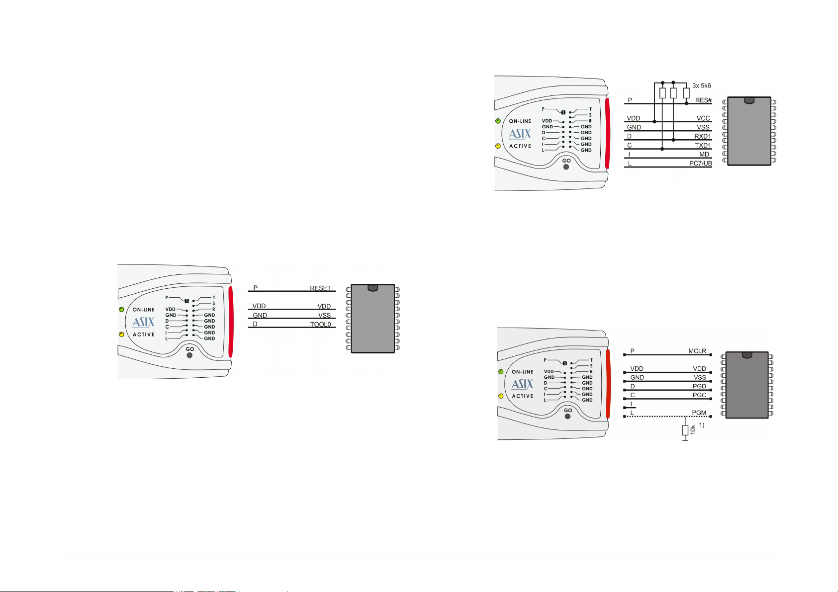
2.6.4 Connection Examples
The following text presents examples of connections
between FORTE and the device being programmed. We
use a notation according to the manufacturer datasheet
of each particular device.
RL78 Microcontrollers
Fig.7: Renesas RL78 microcontroller
RX600 Microcontrollers
Fig.8: Renesas RX600 Microcontroller
1) The RX600 MCUs are programmed in Boot mode.
2) For programming of OSIS(ID) and device locking the
settings in the "FORTE programmer settings" window
have to be used.
PIC Microcontrollers
Fig.9: PIC microcontroller
1) Not all devices have the PGM pin. The PGM pin can
be connected to programmer’s L pin, to VSS via a
pull-down resistor (for HVP programming) or to VDD
via a pull-up resistor (for LVP programming).