03_SM481_Service Manual Installation.pdf - 第10页
Advance d High Speed Flex ible Mounter 3-6 3.1.3. Machine Insta llatio n 3.1.3.1 . Require d Tools Levele r 3 sets (Spe cification: Levele r w it h a ccuracy highe r than 0. 02mm / m) It i s e a sy to use a levele r 10…

Transfer & Installation Procedure
3-5
Caution
If the machine is installed on a floor made of shockabsorbing
material or wood that is not very strong,
excessive vibration may occur during operation. Be sure to
install the machine on a strong and solid floor.
6. Install the machine that was move to the designated place after confirming the place of the
installed line from the responsible personnel of the customer.
7. Remove the vinyl sheet, internal packing material and desiccant.

Advanced High Speed Flexible Mounter
3-6
3.1.3. Machine Installation
3.1.3.1. Required Tools
Leveler 3 sets (Specification: Leveler with accuracy higher than 0.02mm/m) It is easy to use a
leveler 100 mm long with an accuracy of 0.02 mm/m.
Gear wrench for leveling (2 sets)
Vernier calipers
Caution
The approved and calibrated leveler must be used. Its
approval and calibration cycle is 1 year.
3.1.3.2. Installation Procedure of Stand-alone Machine
1. When installing the machine in the In-line system, adjust each foot to match the conveyor
reference surface with the previous and following machines. Align the reference surface
between machines within 0.05mm from the left and right. Remove the front and rear covers
before adjusting the height.
2. Set the reference level of the machine to 900mm and 950mm based on the conveyor surface
(European standard, CE). However, a deviation of ±15 mm is allowed depending on the
condition (inclination) of the floor’s surface.
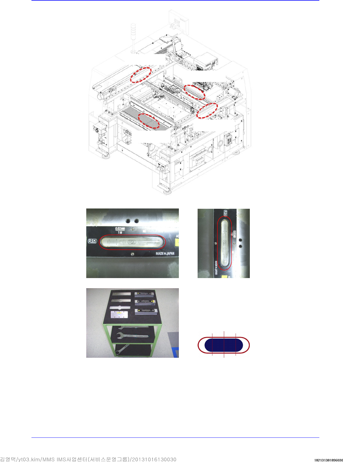
3. Put the level gauges on the upper surfaces of the L/M guides of the Y1 and Y2 axes and on the
upper surface of the front feeder base simultaneously for horizontal alignment. The tolerance is
0.05mm/m (one scale is 0.02mm). The leveler shall be calibrated before use. The calibration
cycle of the leveler is one year.
Measuring points
Y-axis direction
Push the X Gantry to the rear as far as possible and place the head in the middle. Push
the head to the rear side as far as possible, place two level gauges on the middle of the
upper surface of the Y-axis LM Guide and then conduct measurement. (The center of
the level is located on the 12th hole from the LM Guide hole as a reference.).
X-axis direction
Put the level gauge on the middle of the upper surface of the front feeder base and
perform measurement.
Transfer & Installation Procedure
3-7
X-axis leveler Y-axis leveler
Leveler and tools Figure used as reference or marking
Y
-
axis leveler
Y
-
axis leveler
X
-
axis leveler
X-axis leveler