03_SM481_Service Manual Installation.pdf - 第20页
Advance d High Speed Flex ible Mounter 3-16 3.1.7. Motor I/O Che ck 3.1.7.1 . Procedur e 1. Be for e turning on t he m a in circui t bre ake r, che ck again t o de t e r mine if the r e is a ny obstacl e inside t he m ac…
Transfer & Installation Procedure
3-15
Reference
Rating Input voltage: 3 phase AC 200±18V / 208±19V / 220±20V /
240±22V / 380 ±25V / 415±28V, 50/60 Hz
Power consumption: 4.7 KVA
Grounding: Based on 3rd class grounding, the Mega Test
value shall be less than 100 Ω between the ground wire and
the machine.
AVR: The AVR is a basic option. It is recommended to have
the capacity margin at more than 20%.
Caution
When single phase current is taken off from the 3 phase
cur
rent, it is
desirable to use 40% of the total capacity (kW) as single phase current in
order to prevent the machine from being damaged due to distortion
caused by the trip.
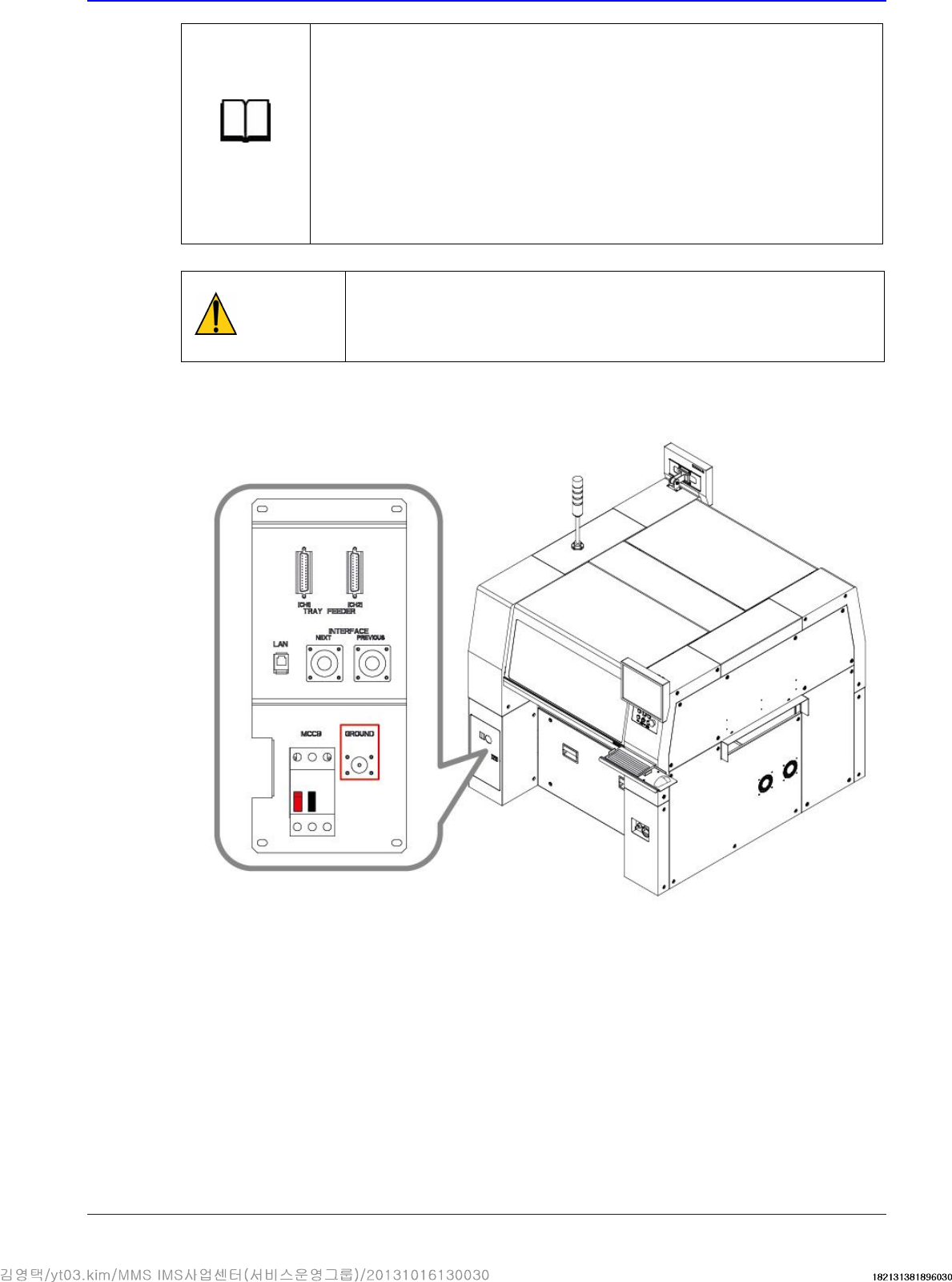
7. The machine must be grounded with peripheral machine by using the FG terminal immediately
below the main power supply connector.
Connect the peripheral
equipment including tray
feeder to the FG terminal..
Advanced High Speed Flexible Mounter
3-16
3.1.7. Motor I/O Check
3.1.7.1. Procedure
1. Before turning on the main circuit breaker, check again to determine if there is any obstacle
inside the machine or on the conveyor.
2. If the area surrounding the machine is clear, turn on the main switch of the machine. At this
time, check if the front and rear emergency switches are released and the front and rear doors
are closed.
Caution
If the power supply and internal of the machine are not
checked before
turning on the main switch, the machine may be damaged or personal
injury may occur. Be sure to check inside and outside of the machine
before turning on the main switch.
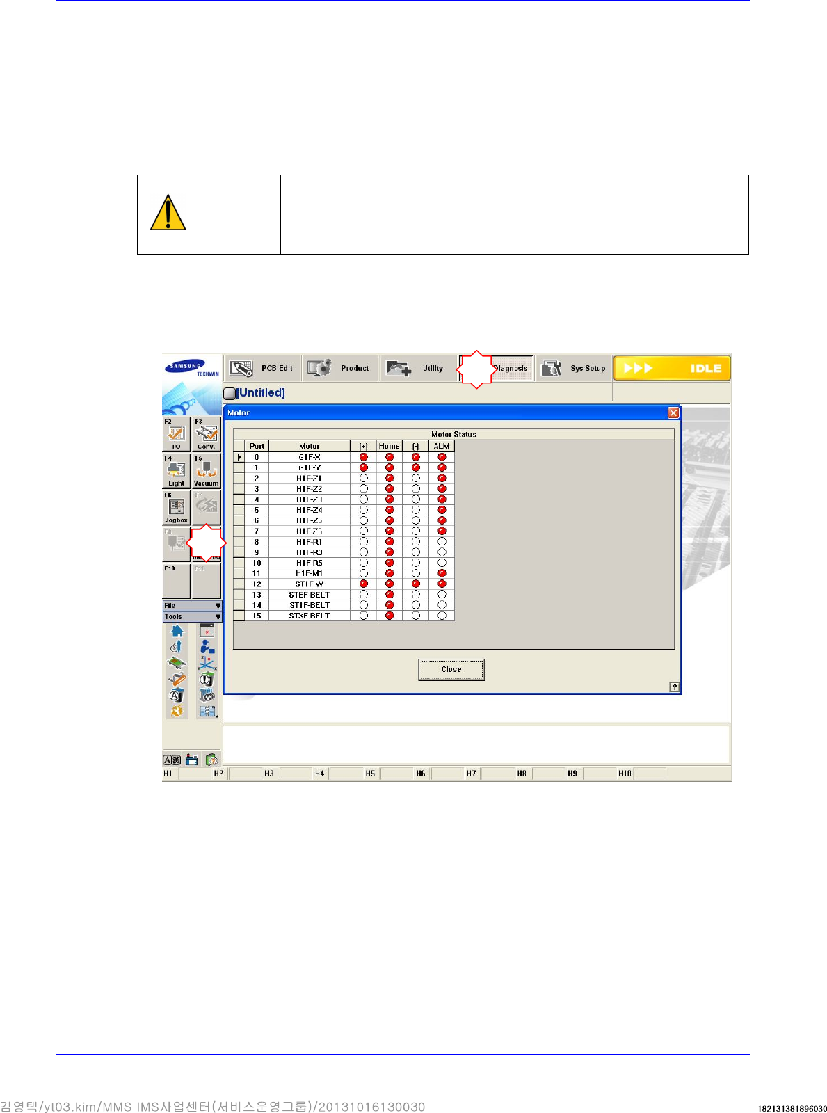
3. If the MMI program is loaded, the I/O of the motor must be checked without pressing the
<Ready> switch on the Front OP Panel. Check if the +/- limit sensor and home sensor operate
normally for each motor by sensing the sensors manually. At this time the XY axes can be
moved manually without difficulty.
1
2
Transfer & Installation Procedure
3-17
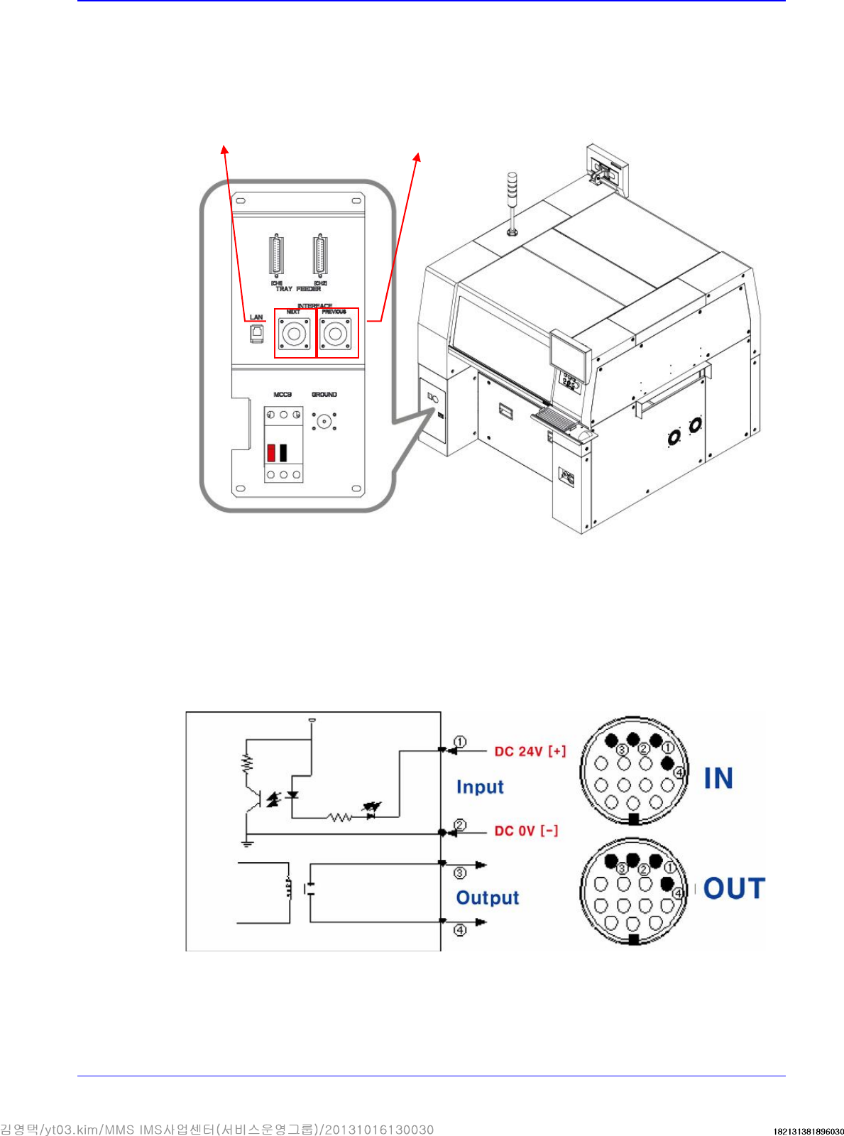
3.1.8. Communication Interface Between Machines
1. Set the communication interface between the printer and chip mounter by referring to the
following.
START Input Signal (Cable No.:①(+),②(-))
The input signal is outputted from the next machine and voltage of approximately 20 ~ 22V is
measured at most input signal terminals.
READY Output Signal (Cable No.:③ , ④)
The output signal is outputted to the previous machine. Generally, at most output signal
terminals, 0Ω is measured when output signal is outputted and ∞Ω is measured when output
signal is not outputted.
The cable connecting
to the next machine
The cable connecting to
the previous machine