03_SM481_Service Manual Installation.pdf - 第14页
Advance d High Speed Flex ible Mounter 3-10 3.1.4. Installation of Parts 3.1.4.1 . Require d Tools T-wren ch (othe r t ools supplied) or hex w r ench Ge ar w rench or torque w r ench Ge ar w rench or torque w r enc…
Transfer & Installation Procedure
3-9
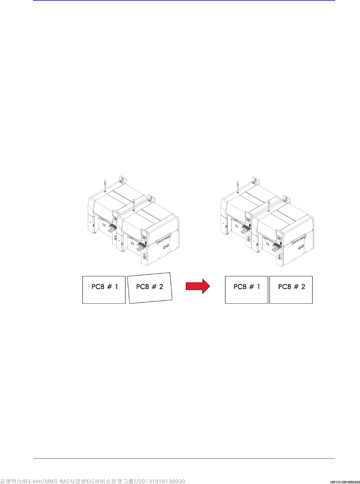
3.1.3.3. In-line installation procedure
The procedure for adjusting the level of the machine is given below.
1. First, align the entry station and exit station based on the fixed frame of the front work station.
Feed the sample PCB in and adjust the conveyor width to the PCB width manually and then
align the conveyor while pushing the PCB as shown in the following figure.
2. After moving the new machine near to the existing one, lower the foot of the machine so that it
is aligned level with the existing machine. Then adjust the level keeping the level difference
below 0.05mm/m. (Any slight difference in level can be felt using a finger tip.)
3. Using a lever, move the machine to the position where the gap between the existing machine
and the edge of the conveyor can be kept between 3~5mm.
4. Perform the procedure of leveling the machine again. (Refer to “2.1.3.2 Installation procedure
for stand alone“.)
5. Put the PCBs on each conveyor of the two machines, and set the machines so that the level
difference is 0.05~0.50mm, enough to allow the PCBs to move downward. Essentially, the
slope of the conveyor shall be set to allow for the “Downflow” of the PCB in the direction in
which the PCB is moving.
6. To ensure the straight movement of the PCB between machines, the machines must be installed
correctly so that there will be no unparallel gap at either front or rear side of the PCB, when the
PCB is tightly contacted to the reference line.
7. Adjust the machine level until there is no blocking sound at the gap between machines while
pushing the PCB slowly.
8. In the case of level adjustment between two machines, if the leveling of the postprocess
machine was finished but the level does not match with the conveyor of the pre-process
machine, perform as follows. The level of the reference surface must be identical in the left and
right side direction of the PCB (PCB flow direction), and the level difference must be less than
0.1mm/m in the front and rear side direction of the PCB. The PCB must pass smoothly without
being blocked when it is pushed through the machines by hand at low speed.
9. For the next procedure, refer to “ Installation procedure for stand alone“.
Advanced High Speed Flexible Mounter
3-10
3.1.4. Installation of Parts
3.1.4.1. Required Tools
T-wrench (other tools supplied) or hex wrench
Gear wrench or torque wrench
Gear wrench or torque wrench
3.1.4.2. Part list
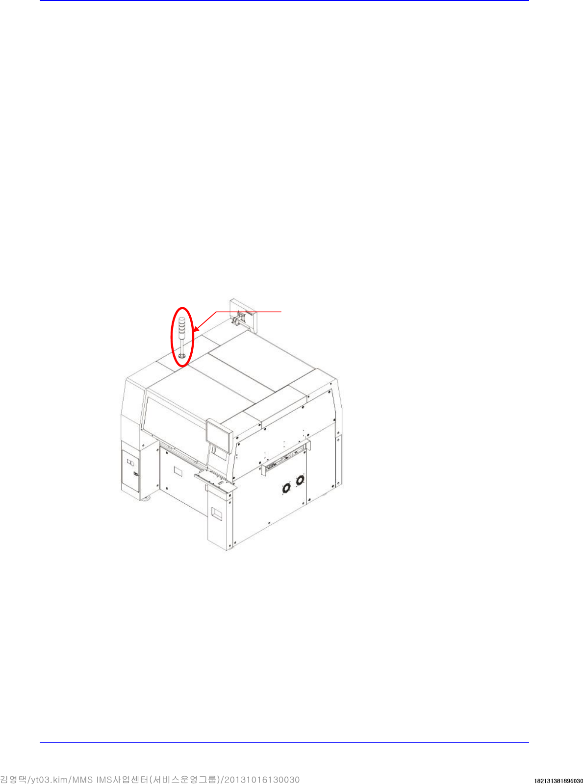
Tower lamp
Mouse and mouse pad
Keyboard
Monitor and monitor stand
3.1.4.3. Part Installation Procedure
1. Install the monitor base after leveling and install the monitor by connecting the connector on
the upper part of the machine. (Tighten all bolts when assembling the monitor unit.)
2. Connect the connector at the left inside the machine and signal light connector and secure the
signal light at the left on the upper part with fixing bolts (4 sets).
Signal Light
Transfer & Installation Procedure
3-11
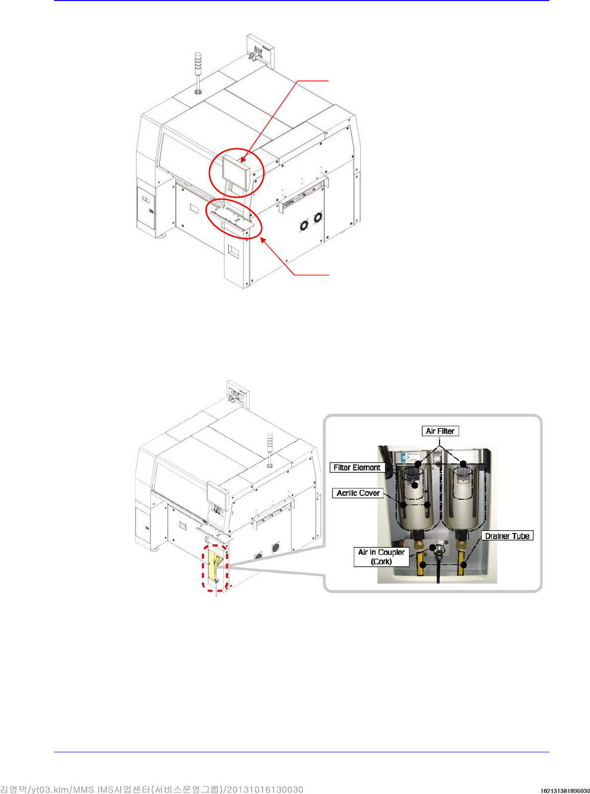
3. Install the keyboard bracket on the upper front cover and install the keyboard, mouse, etc.
3.1.5. Pneumatic Pressure Setup and Cable Connection
1. Connect pneumatic hose to the left fitting of the air filter. At this time, Check if the air filter is
installed or not in the air main source device.
Monitor
Keyboard Stand