03_SM481_Service Manual Installation.pdf - 第22页
Advance d High Speed Flex ible Mounter 3-18 If the I/F connec tors of neighboring m ac hine s ar e dif f e r en t, cut the c able and connec t it refe rring to the following f igure . Machine s manufactured not i n a…
Transfer & Installation Procedure
3-17
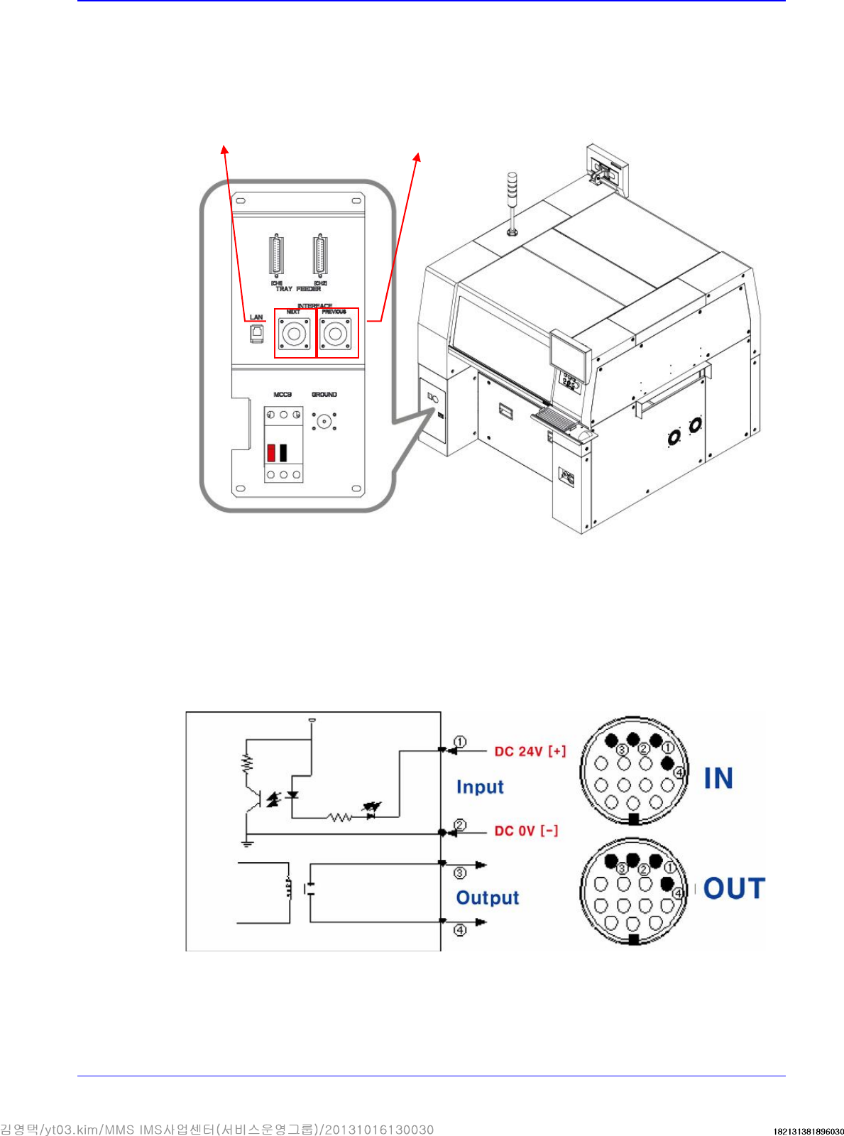
3.1.8. Communication Interface Between Machines
1. Set the communication interface between the printer and chip mounter by referring to the
following.
START Input Signal (Cable No.:①(+),②(-))
The input signal is outputted from the next machine and voltage of approximately 20 ~ 22V is
measured at most input signal terminals.
READY Output Signal (Cable No.:③ , ④)
The output signal is outputted to the previous machine. Generally, at most output signal
terminals, 0Ω is measured when output signal is outputted and ∞Ω is measured when output
signal is not outputted.
The cable connecting
to the next machine
The cable connecting to
the previous machine
Advanced High Speed Flexible Mounter
3-18
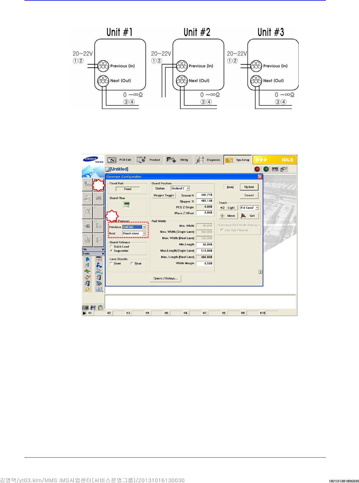
If the I/F connectors of neighboring machines are different, cut the cable and connect it
referring to the following figure.
Machines manufactured not in accordance with the SMEMA code such as SIMENS, SANYO
and TDK (RX-11), and machines without dual contact interface shall be examined specially.
Machine interface must be decided. (Select 2-contact method or SMEMA method suitable for
the user’s environment.).
Select SYS.SETUP menu and lower menu of the conveyor.
Select ‘Stand Alone’, or SSA Type (2 contacts), or SMEMA in the ‘In (Before) and Out (After)’
combo box of the inline protocol area.
- Stand Alone: The connection is not established between machines. Setup is made during
manual operation.
- SSA Type: The PCB flows only if the contact is connected in the next machine.
- SMEMA: The ready signal is given by the previous machine (24V), and the contact is
connected in the next machine.
Check if the interface between connected machines operates normally by using the MMI
bypass function. At this time, perform test using at least 3 pieces of PCB.
2
3
Transfer & Installation Procedure
3-19
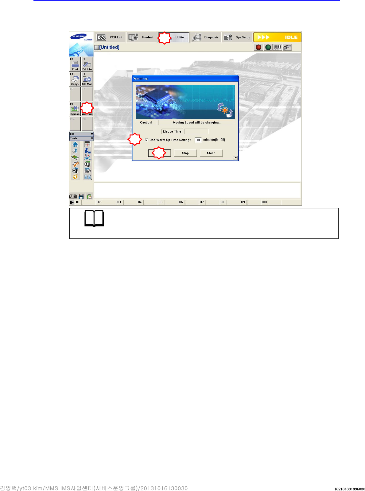
3.1.9. Warming Up
After the machine installation, warm up the machine for 30 minutes.
Reference
Check if there is the abnormal noise from machine and machine operation is
normal or not for the warm-up
1
2
3
4