03_SM481_Service Manual Installation.pdf - 第9页
T ransfer & Installation Pr ocedur e 3-5 Caution If the machine is inst alled on a floor made of sh ockabsorbing material or wood that is not very stro ng, excessive vibration ma y occur during operation. B e sure to…
Advanced High Speed Flexible Mounter
3-4
3.1.2. Unpacking and Transportation
3.1.2.1. Required Tools
Forklift and hand lift
Wrench set, wrench drill
3.1.2.2. Unpacking Procedure
1. Remove the external carton box and steel packing material.
2. Check if the quantity of the spare parts in the spare part list is the same as the number of spare
part packing boxes..
3. Move the machine’s components to the location where the machine is to be installed.
Caution
If the machine is unpacked by imposing excessive impact
on it, the machine cover may be damaged. Do not unpack
the machine by imposing excessive impact on it.
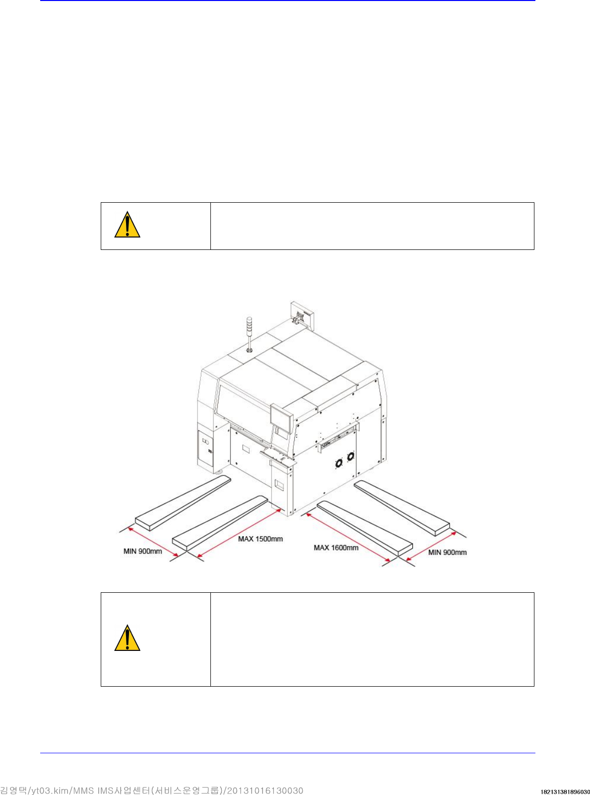
4. Adjust the lift arm width of the forklift referring to the following figure before moving the
machine.
Caution
If the lift arm (fork) contacts the bottom of the cover, the
cover may be damaged. The upper surface of the lift arm
(fork) must contact the flat area of the lower frame of the
machine.
In addition, check the position of the lift arm (fork) to prevent
the machine from inclining and the foot or caster of the
machine from being damaged.
5. When transporting the machine to the designated location after unloading the machine from the
pallet, raise the feet of the machine completely and move it using a handlift.

Transfer & Installation Procedure
3-5
Caution
If the machine is installed on a floor made of shockabsorbing
material or wood that is not very strong,
excessive vibration may occur during operation. Be sure to
install the machine on a strong and solid floor.
6. Install the machine that was move to the designated place after confirming the place of the
installed line from the responsible personnel of the customer.
7. Remove the vinyl sheet, internal packing material and desiccant.

Advanced High Speed Flexible Mounter
3-6
3.1.3. Machine Installation
3.1.3.1. Required Tools
Leveler 3 sets (Specification: Leveler with accuracy higher than 0.02mm/m) It is easy to use a
leveler 100 mm long with an accuracy of 0.02 mm/m.
Gear wrench for leveling (2 sets)
Vernier calipers
Caution
The approved and calibrated leveler must be used. Its
approval and calibration cycle is 1 year.
3.1.3.2. Installation Procedure of Stand-alone Machine
1. When installing the machine in the In-line system, adjust each foot to match the conveyor
reference surface with the previous and following machines. Align the reference surface
between machines within 0.05mm from the left and right. Remove the front and rear covers
before adjusting the height.
2. Set the reference level of the machine to 900mm and 950mm based on the conveyor surface
(European standard, CE). However, a deviation of ±15 mm is allowed depending on the
condition (inclination) of the floor’s surface.
3. Put the level gauges on the upper surfaces of the L/M guides of the Y1 and Y2 axes and on the
upper surface of the front feeder base simultaneously for horizontal alignment. The tolerance is
0.05mm/m (one scale is 0.02mm). The leveler shall be calibrated before use. The calibration
cycle of the leveler is one year.
Measuring points
Y-axis direction
Push the X Gantry to the rear as far as possible and place the head in the middle. Push
the head to the rear side as far as possible, place two level gauges on the middle of the
upper surface of the Y-axis LM Guide and then conduct measurement. (The center of
the level is located on the 12th hole from the LM Guide hole as a reference.).
X-axis direction
Put the level gauge on the middle of the upper surface of the front feeder base and
perform measurement.