03_SM481_Service Manual Installation.pdf - 第21页
T ransfer & Installation Pr ocedur e 3-17 3.1.8. Co mm uni cat ion Interface Betw een Machines 1. Set the communic ation i nte rfac e between t he pr inter a nd c hip mo unter by r efe rring t o th e follow ing. ST…
Advanced High Speed Flexible Mounter
3-16
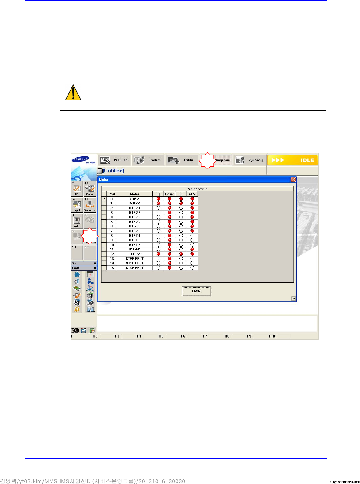
3.1.7. Motor I/O Check
3.1.7.1. Procedure
1. Before turning on the main circuit breaker, check again to determine if there is any obstacle
inside the machine or on the conveyor.
2. If the area surrounding the machine is clear, turn on the main switch of the machine. At this
time, check if the front and rear emergency switches are released and the front and rear doors
are closed.
Caution
If the power supply and internal of the machine are not
checked before
turning on the main switch, the machine may be damaged or personal
injury may occur. Be sure to check inside and outside of the machine
before turning on the main switch.
3. If the MMI program is loaded, the I/O of the motor must be checked without pressing the
<Ready> switch on the Front OP Panel. Check if the +/- limit sensor and home sensor operate
normally for each motor by sensing the sensors manually. At this time the XY axes can be
moved manually without difficulty.
1
2
Transfer & Installation Procedure
3-17
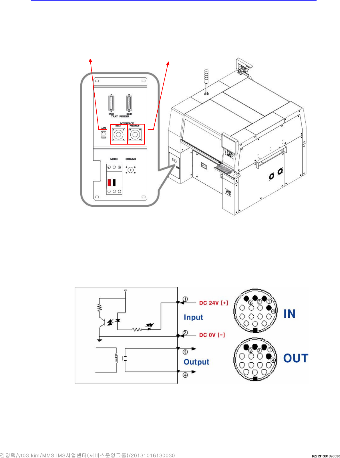
3.1.8. Communication Interface Between Machines
1. Set the communication interface between the printer and chip mounter by referring to the
following.
START Input Signal (Cable No.:①(+),②(-))
The input signal is outputted from the next machine and voltage of approximately 20 ~ 22V is
measured at most input signal terminals.
READY Output Signal (Cable No.:③ , ④)
The output signal is outputted to the previous machine. Generally, at most output signal
terminals, 0Ω is measured when output signal is outputted and ∞Ω is measured when output
signal is not outputted.
The cable connecting
to the next machine
The cable connecting to
the previous machine
Advanced High Speed Flexible Mounter
3-18
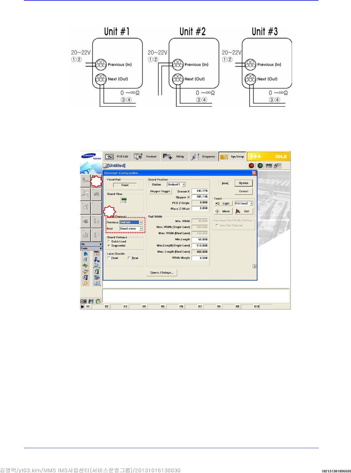
If the I/F connectors of neighboring machines are different, cut the cable and connect it
referring to the following figure.
Machines manufactured not in accordance with the SMEMA code such as SIMENS, SANYO
and TDK (RX-11), and machines without dual contact interface shall be examined specially.
Machine interface must be decided. (Select 2-contact method or SMEMA method suitable for
the user’s environment.).
Select SYS.SETUP menu and lower menu of the conveyor.
Select ‘Stand Alone’, or SSA Type (2 contacts), or SMEMA in the ‘In (Before) and Out (After)’
combo box of the inline protocol area.
- Stand Alone: The connection is not established between machines. Setup is made during
manual operation.
- SSA Type: The PCB flows only if the contact is connected in the next machine.
- SMEMA: The ready signal is given by the previous machine (24V), and the contact is
connected in the next machine.
Check if the interface between connected machines operates normally by using the MMI
bypass function. At this time, perform test using at least 3 pieces of PCB.
2
3